Cross-flow reactor and method

a cross-flow reactor and cross-flow technology, which is applied in the direction of liquid-gas reaction processes, chemistry apparatus and processes, coatings, etc., can solve the problems of increased non-uniformity of processes within the reaction chamber, non-uniform gas flow between the reaction chambers, and inability to form a complete seal, etc., to achieve facilitate consistent spacing

Active Publication Date: 2016-09-15
ASM IP HLDG BV
View PDF6 Cites 303 Cited by
  • Summary
  • Abstract
  • Description
  • Claims
  • Application Information

AI Technical Summary

Benefits of technology

[0009]In accordance with various embodiments of the disclosure, a gas-phase reactor includes a cross-flow reaction chamber comprising a tapered top surface and a bottom surface comprising a portion of a base plate and a portion of a top surface of a susceptor, a gas diffuser coupled to an inlet of the reaction chamber, and an exhaust coupled to the outlet of the reaction chamber. In accordance with various aspects of these embodiments, a distance between the tapered top surface and the top surface of the susceptor and / or base plate is greater proximate the inlet relative to a distance between the tapered top surface and the top surface of the susceptor and / or base plate at the outlet. In accordance with other aspects, the distance between the tapered top surface and the top surface of the susceptor and / or base plate is greater proximate the outlet relative to a distance between the tapered top surface and the top surface of the susceptor and / or base plate at the inlet. In accordance with further aspects, the tapered surface comprises a linearly tapered surface. A distance between the tapered top surface and the top surface of the susceptor and / or base plate at or proximate the inlet can range between about 1 mm and about 10 mm. Similarly, a distance between the tapered top surface and the top surface of the susceptor and / or base plate at or proximate the outlet can range between about 1 mm and about 10 mm. Gas-phase reactors in accordance with further exemplary aspects can include at least one spacer, such as a pin, between the susceptor and the base plate. Use of the spacer facilitates consistent spacing between the susceptor and the base plate, while still allowing flow between a region, such as a load or transition region within the reactor, and the reaction chamber. In accordance with further embodiments, a gap between the susceptor and the baseplate includes a vertical and / or horizontal gap section.

Problems solved by technology

However, because of the relatively small reaction chamber, cross-flow reactors tend to exhibit a pressure drop from the gas inlet side of the reaction chamber to the flow outlet side of the reaction chamber.
Thus, the pressure drop within the reaction chamber can cause differences in adsorption / reaction rates along a surface of a substrate—e.g., between a leading and training edge of the substrate—which in turn can lead to increased non-uniformity of processes within the reaction chamber.
Another problem associated with cross-flow reactors is non-uniform gas flow between the reaction chamber and, for example a lower or load / unload area within the reactor.
Many reactors do not form a complete seal between the reaction chamber and the load / unload area, but rather allow a controlled gas flow between the two areas.
The non-uniform pressure can, in turn, lead to backside and edge deposition on or reaction with the substrate and other problems.

Method used


Image

  • Cross-flow reactor and method
  • Cross-flow reactor and method
  • Cross-flow reactor and method

Examples


Embodiment Construction

[0023]The description of exemplary embodiments provided below is merely exemplary and is intended for purposes of illustration only; the following description is not intended to limit the scope of the disclosure or the claims. Moreover, recitation of multiple embodiments having stated features is not intended to exclude other embodiments having additional features or other embodiments incorporating different combinations of the stated features.

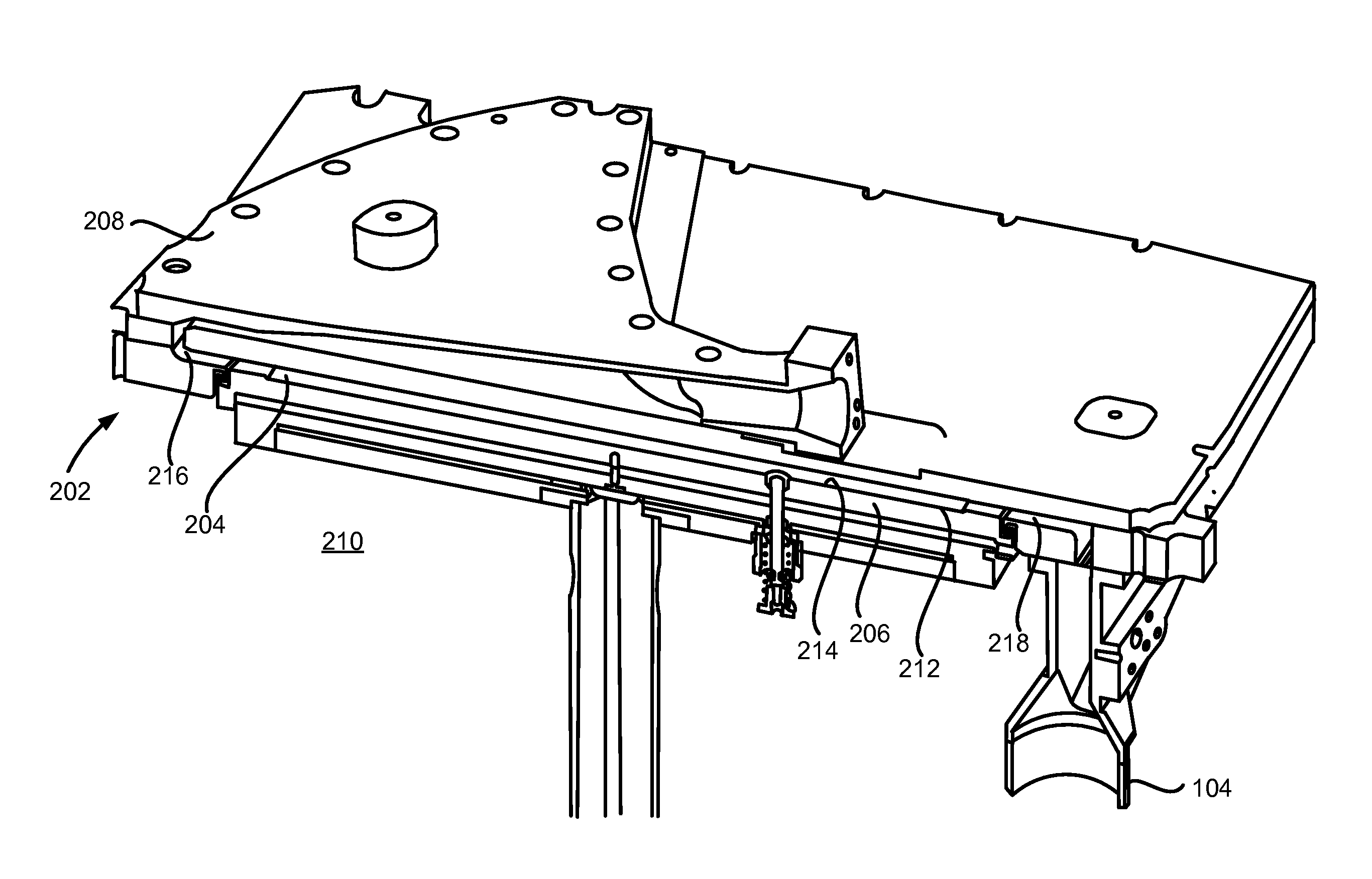
[0024]As set forth in more detail below, various embodiments of the disclosure relate to gas-phase reactors and reactor systems that include a variable-height reaction chamber and / or a spacer to help define a gap between a susceptor and a base plate of the reactor.

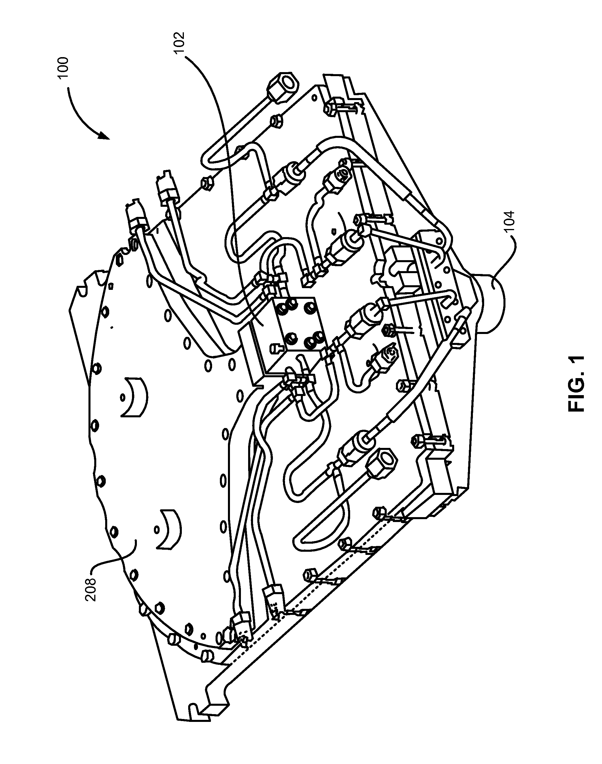
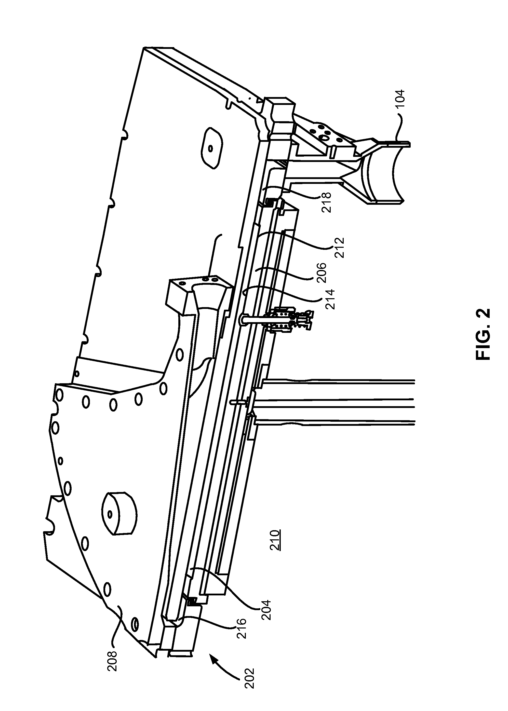
[0025]FIGS. 1-5 illustrate portions or sections of a gas-phase reactor system 100 in accordance with exemplary embodiments of the disclosure. System 100 includes a reactor 202, including a reaction chamber 204, a susceptor 206, a diffuser 208, a mixer 102, a reaction chamber exhaust ...


PUM

PropertyMeasurementUnit
distanceaaaaaaaaaa
distanceaaaaaaaaaa
distanceaaaaaaaaaa

Abstract

Gas-phase reactors and systems are disclosed. Exemplary reactors include a reaction chamber having a tapered height. Tapering the height of the reactor is thought to reduce a pressure drop along the flow of gasses through the reactor. Exemplary reactors can also include a spacer within a gap to control a flow of gas between a region and a reaction chamber.

Description

FIELD OF DISCLOSURE[0001]The present disclosure generally relates to gas-phase apparatus and methods. More particularly, the disclosure relates to cross-flow reactors and components, systems including the reactors and components, and methods of using the reactors, components, and systems.BACKGROUND OF THE DISCLOSURE[0002]Gas-phase reactors, such as chemical vapor deposition (CVD) reactors, including, for example atomic layer deposition (ALD) reactors, can be used for a variety of applications, including forming layers on a substrate surface. Such reactors can be used to deposit, etch, clean, and / or treat layers on a substrate to form semiconductor devices, flat panel display devices, photovoltaic devices, microelectromechanical systems (MEMS), and the like.[0003]A typical gas-phase reactor system includes a reactor including a reaction chamber, one or more precursor gas sources fluidly coupled to the reaction chamber, one or more carrier or purge gas sources fluidly coupled to the r...

Claims


Application Information

Patent Timeline
Patent Type & Authority Applications(United States)
IPC IPC(8): H01J37/32B08B7/00C23C16/455
CPCH01J37/32449B08B7/00H01J37/32816C23C16/45544B01J10/00C23C16/455H01J37/32458C23C16/45557C23C16/4583
Inventor WHITE, CARL LOUISSHERO, ERIC JAMESVERGHESE, MOHITH
Owner ASM IP HLDG BV
Why Eureka
Try Eureka