This helps you quickly interpret patents by identifying the three key elements:
Problems solved by technology
Method used
Benefits of technology
Benefits of technology
The technical problem addressed in this patent is to provide an ultrasonic transmitter that overcomes the limitations of previous designs and meets the needs of modern technology. The solution provided is an ultrasonic transmitter that satisfies these requirements.
Problems solved by technology
This type of transmitter does not work effectively in transmission through air and, in particular, it is subject to a drawback explained below.
However, the constant compression between front mass and backing greatly reduces the freedom of movement of the piezoelectric elements, which constitutes a limit to the power delivered and, in practice, limits the effectiveness of using the known transmitters.
In particular, the known solution cannot be usefully employed in transmission through air, for example for the purpose of detecting a lack of homogeneity in wood panels.
Method used
Image
Click on the blue label to locate the original text in one second.
Reading with bidirectional positioning of images and text.
Examples
first embodiment
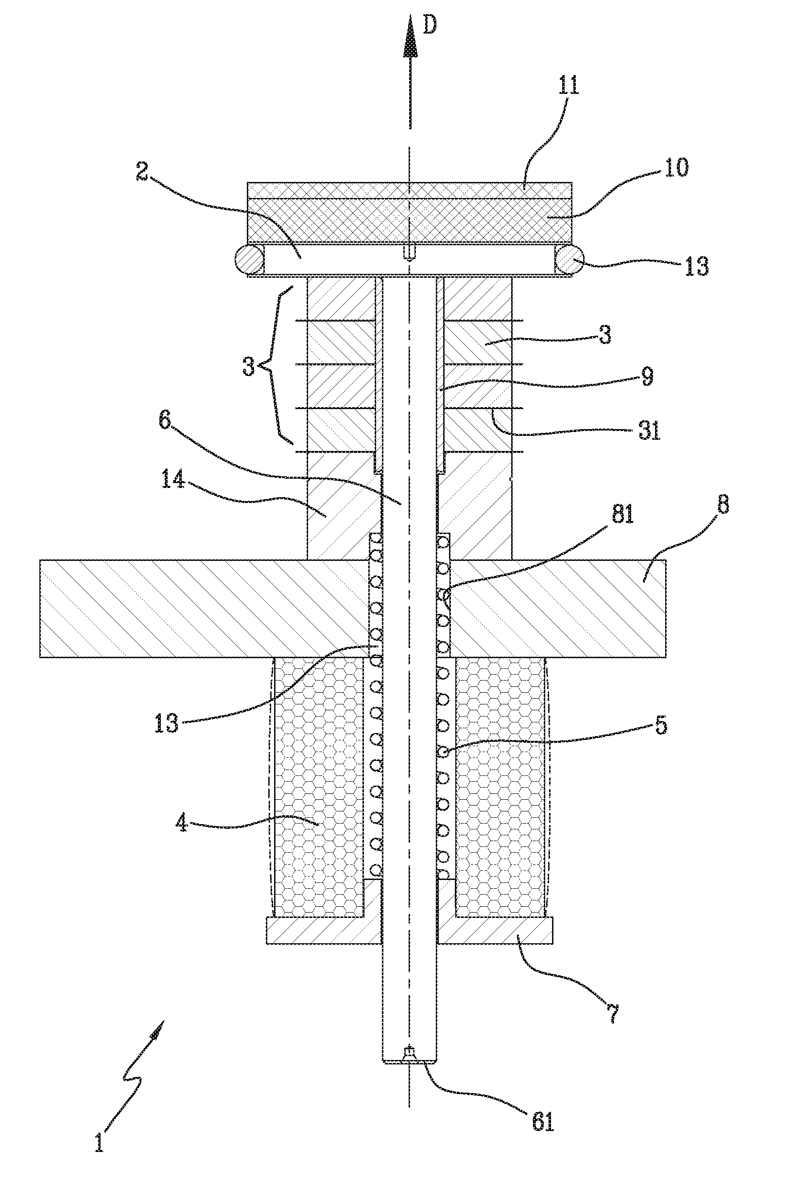
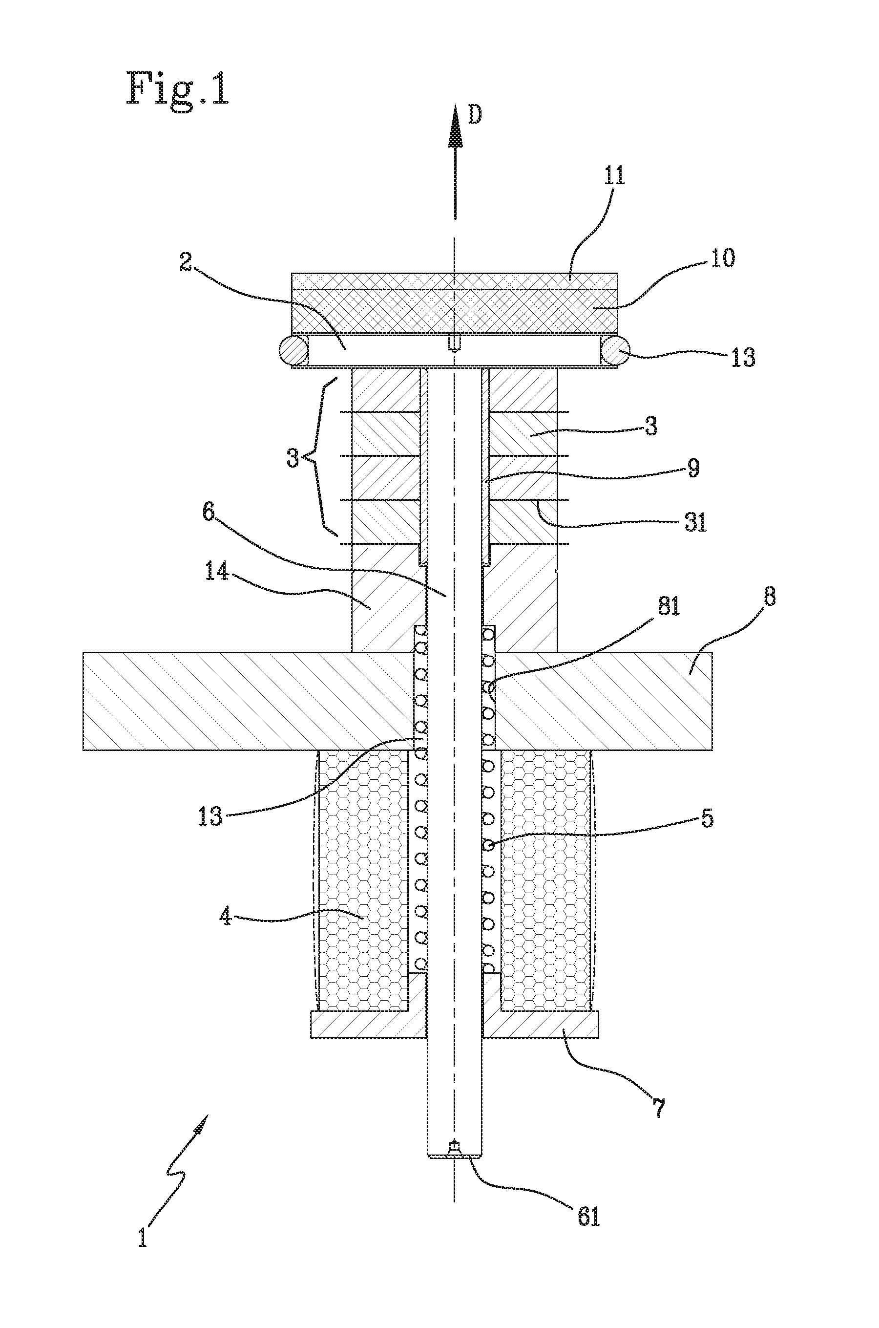
[0051]In the invention, illustrated in FIG. 1, the biasing means 4, 5 can include one or more elastic elements 4 made up of elastomeric material, sandwiched between the shoulder 7 and the support 8 and / or a spring 5, for example of the spiral type, located in an internal cavity 13 of the transmitter 1, in which the rod 6 slides.
[0052]Preferably, the biasing means 4, 5 is equipped both with the elastomeric elements and the spring 5.
[0053]The latter can be positioned within the elastomeric elements and extend between said metalbushing 14, in which the internal cavity 13 is at least partly fashioned, and the shoulder 7.
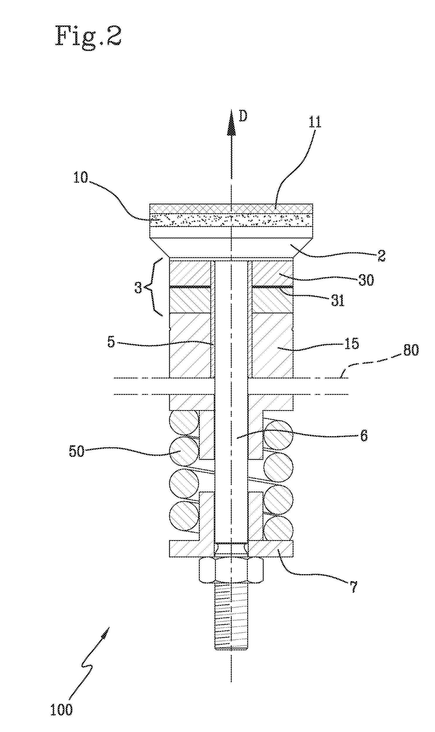
[0054]In the second embodiment, the biasing means can comprise an external spring 5, as in the example in FIG. 2, or can be constructed as in the first embodiment.
[0055]In the first embodiment of the invention, as said, a rear part of the transmitter 1 comprises both the above-mentioned support 8 and the bushing 14 (FIG. 1).
[0056]The configuration of the rear part 8, 14...
second embodiment
[0062]In the second embodiment, the rear part of the transmitter 100 likewise comprises a metalbushing 15, located in contact with the piezoelectric means 3.
[0063]In this case, however, the bushing 15 is made up of a heavy material, such as, for example, steel or tungsten, which has the function of reflecting, toward the head 2, the power that in turn is reflected away from the head due to the small but inevitable impedance mismatch between the piezoelectric means 3 and the head 2 itself.
[0064]As said, the invention has been conceived above all for transmission through air; therefore, the aforesaid front mass preferably also includes comprising adapter means 10, 11 arranged in contact with the head 2 and suitable for enabling matching of acoustic impedance between the piezoelectric means 3 and air.
[0065]In detail, the adapter means 10, 11 is located on the outermost side of the transmission head 2, i.e. the side from which it emits ultrasound.
[0066]The adapter means can comprise at...
PUM
Abstract
An ultrasonic transmitter (1, 100) includes a shaped transmission head (2) and piezoelectric element (3) arranged for contacting said shaped head (2).The head (2) is movable within the transmitter (1), which includes biasing element (4, 5, 50) suitable for urging the head (2) and the piezoelectric element (3) so as to maintain their mutual contact during repeated dimensional changes of the piezoelectric element (3).
Description
FIELD OF THE INVENTION[0001]The present invention relates to an ultrasonic transmitter, especially but not solely intended to detect a lack of homogeneity in wood products, such as, for example panels made by pressing incoherent materials of a ligneous nature.BACKGROUND OF THE INVENTION[0002]The practice of performing a check for the lack of homogeneity on wood panels or layers while, after forming, they are made to pass along a processing line is well known.[0003]This check is performed by means of an apparatus that essentially comprises a plurality of devices for emitting (or transmitting) sound waves, in particular of an ultrasonic frequency, which operate on one side of the panel in transit, and a plurality of receiving devices operating on the opposite side of the same panel at a pre-established distance from the emitters.[0004]Though experience has proven the effectiveness of this type of solution, a need has arisen to have a transmitter that enables a better resolution in che...
Claims
Application Information
Patent Timeline
Application Date:The date an application was filed.
Publication Date:The date a patent or application was officially published.
First Publication Date:The earliest publication date of a patent with the same application number.
Issue Date:Publication date of the patent grant document.
PCT Entry Date:The Entry date of PCT National Phase.
Estimated Expiry Date:The statutory expiry date of a patent right according to the Patent Law, and it is the longest term of protection that the patent right can achieve without the termination of the patent right due to other reasons(Term extension factor has been taken into account ).
Invalid Date:Actual expiry date is based on effective date or publication date of legal transaction data of invalid patent.

