Power transmission shaft

a technology of transmission shaft and transmission shaft, which is applied in the direction of engine seals, yielding couplings, couplings, etc., can solve the problems of increasing installation time and manufacturing costs, and achieve the effect of suppressing the impact absorption potential

Active Publication Date: 2016-09-22
HITACHI ASTEMO LTD
View PDF13 Cites 6 Cited by
  • Summary
  • Abstract
  • Description
  • Claims
  • Application Information

AI Technical Summary

Benefits of technology

[0007]It is, therefore, in view of the previously-described drawbacks of the prior art, an object of the invention to provide an improved power transmission shaft configured to suppress the outside diameter of the power transmission shaft from enlarging and to suppress the number of parts of the power transmission shaft from increasing, while suppressing an impact absorbing potential from lowering during relative displacements of a tubular member and a shaft member in the two opposite axial directions.

Problems solved by technology

The prior-art power transmission device suffers the disadvantages, that is, the large-sized outside diameter of the power transmission shaft enlarged due to the outside diameter of the boot and increased number of parts (leading to increased installation time and manufacturing costs) because of fixing of both ends of the boot by means of respective boot bands.

Method used


Image

  • Power transmission shaft
  • Power transmission shaft
  • Power transmission shaft

Examples


first embodiment

Operation of First Embodiment

[0045]With the previously-discussed arrangement, the power transmission shaft of the first embodiment operates as follows:

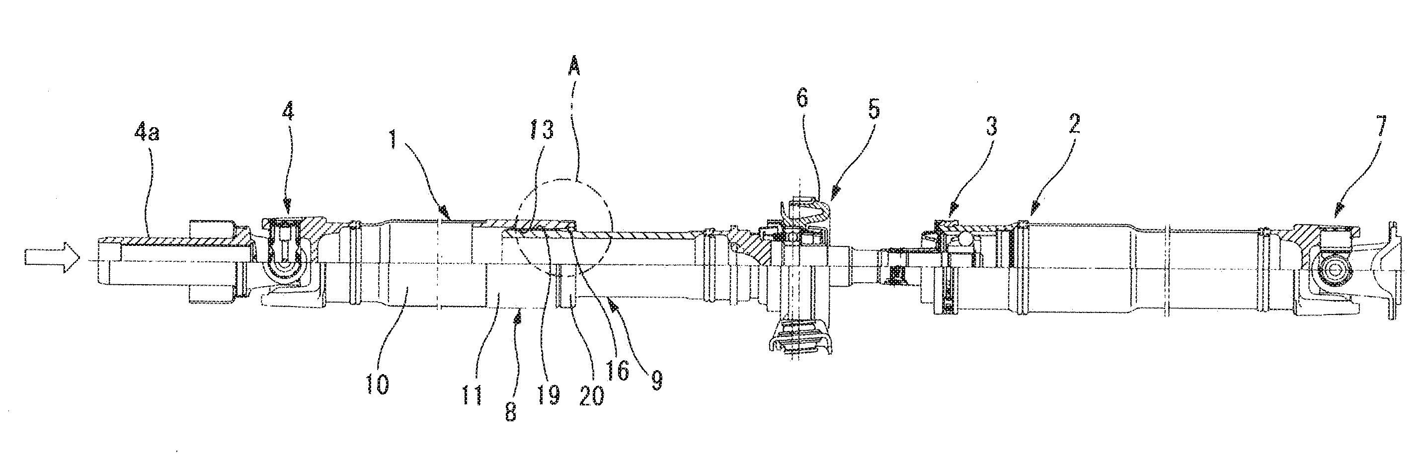
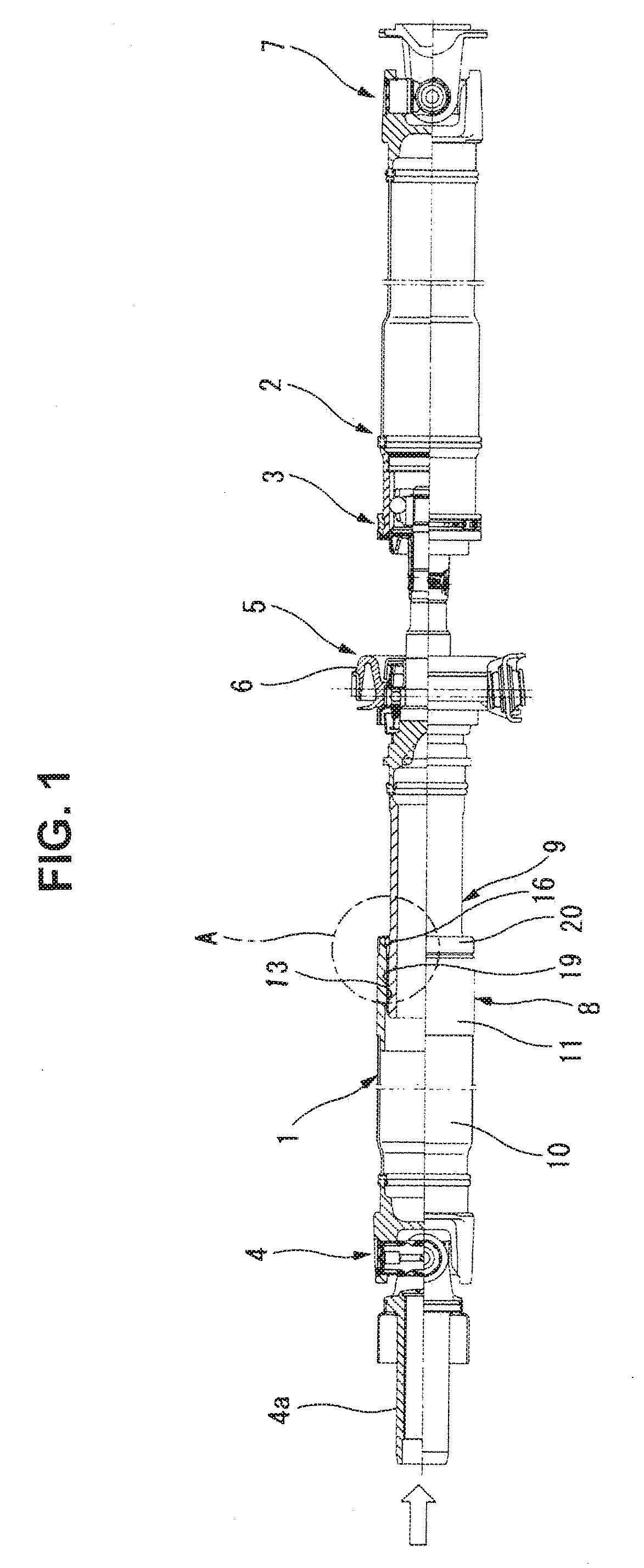
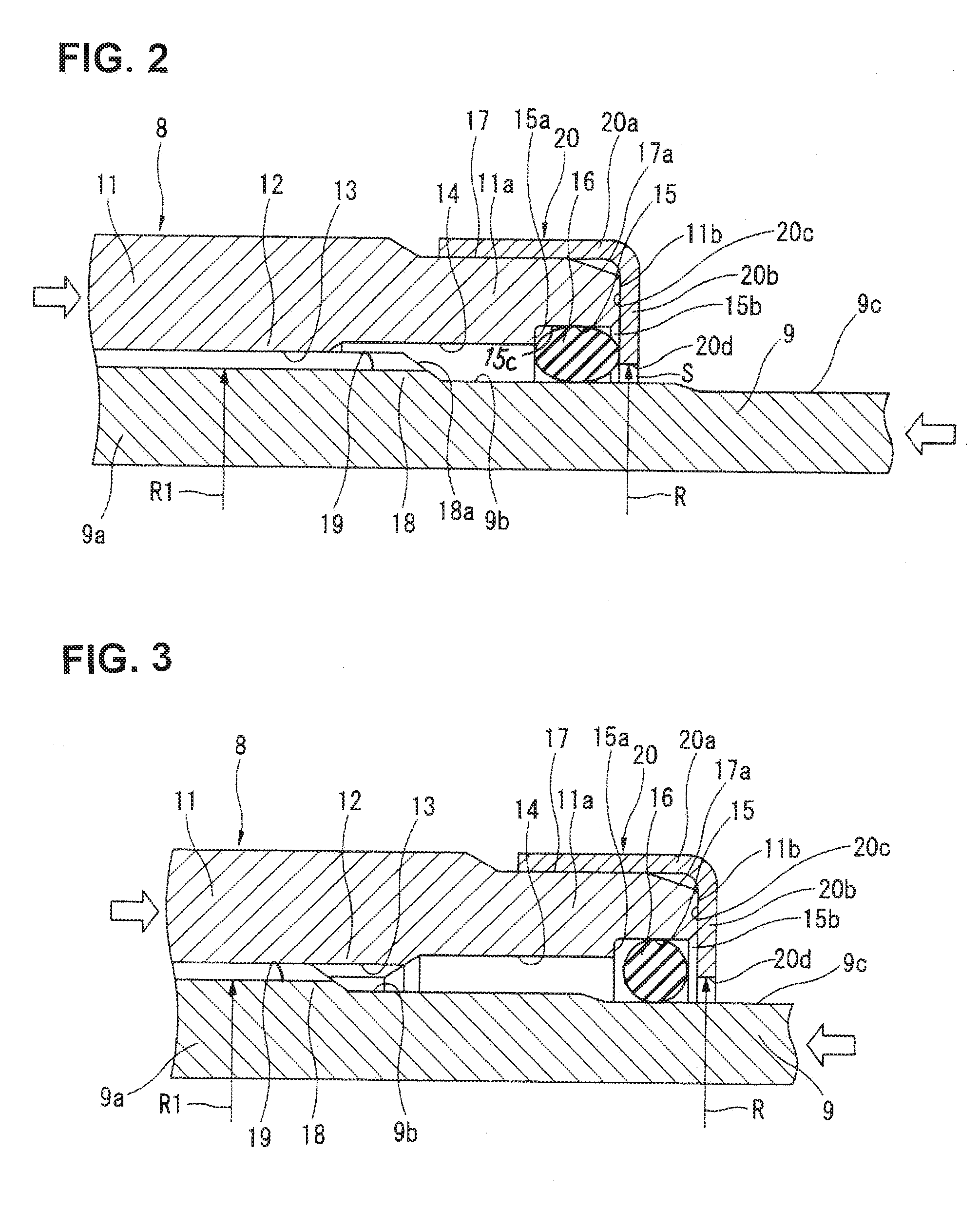
[0046]For instance, during a vehicle collision, when an excessive input load is applied from the side of the transfer through the first cruciform joint 4 to the front-side shaft 8 of the shaft 1 (see the left-hand side voided arrow of FIG. 2), a large force is exerted on the second tube 11 of the front-side shaft 8 in an axially rearward direction such that the second tube 11 is axially displaced toward the rear-side shaft 9 via the spline joint (i.e., female spline joint portion 13 and male spline joint portion 19 spline-connected each other). Also, during a vehicle collision, when an excessive input load is applied from the side of the rear differential through the second cruciform joint 7 to the rear-side shaft 9 of the shaft 1 (see the right-hand side voided arrow of FIG. 2), a large force is exerted on the rear-side shaft 9 in an...

second embodiment

[0065]Referring to FIG. 5, there is shown the power transmission shaft (the vehicle propeller shaft) of the second embodiment. Seal housing groove 15 is formed in the distal part of the cylindrical inner peripheral surface 14 at an axial position somewhat spaced apart from the rearmost end face of the rear end 11a of the second tube 11. Additionally, a diametrically-enlarged retainer housing annularly recessed groove (simply, retainer housing groove) 21 is formed axially outside of the seal housing groove 15, such that these grooves 15 and 21 are juxtaposed to each other. A diametrically-expanding / contracting, elastically deformable snap-action retainer member 22 is held in the retainer housing groove 21.

[0066]The rear-half inner peripheral surface (the right-hand side inner peripheral surface, viewing FIG. 5) of the opening 11c of the rear end 11a of the second tube 11 is configured as an annular surface having a uniform inside diameter. On the other hand, the front-half inner peri...

third embodiment

[0075]Referring to FIG. 6, there is shown the power transmission shaft (the vehicle propeller shaft) of the third embodiment. A seal member 24 and a retainer member 23 are united with each other. That is, seal member 24 and retainer member 23 are formed integral with each other and configured as a so-called oil-seal structure.

[0076]That is, seal housing groove 15 is formed in the cylindrical inner peripheral surface of the rearmost end portion of the rear end 11a of the second tube 11 and configured as an annular surface having a uniform inside diameter.

[0077]As shown in FIG. 6, retainer member 23 is formed and bent into a substantially C-shape in cross-section. Retainer member 23 is comprised of an outer cylinder part 23a press-fitted into the inner peripheral surface of seal housing groove 15 and a retainer part 23b bent to extend in the direction perpendicular to the axial direction of the second tube 11. The outside diameter of outer cylinder part 23a is dimensioned to be slight...


PUM


Abstract

In a power transmission shaft including a rear-side shaft having a male spline joint portion formed on the outer periphery of a front end of the rear-side shaft and a tubular front-side shaft having a female spline joint portion formed on the inner periphery of a rear end of the tubular front-side shaft, a seal ring is housed in a seal housing groove configured at the rear end of the tubular front-side shaft. The seal ring is interposed between an outer peripheral seal surface of the rear-side shaft and an inner peripheral surface of the seal housing groove with a compressive deformation. Additionally, the seal ring is sandwiched and retained between the inside wall surface of the seal housing groove and the inside end face of a disk-shaped retainer part of a retainer press-fitted to the rear end of the tubular front-side shaft.

Description

TECHNICAL FIELD[0001]The present invention relates to the improved technology of a power transmission shaft that transmits power from a transmission of a vehicle drive road wheels.BACKGROUND ART[0002]In recent years, a power transmission shaft, for example a propeller shaft which is installed on a vehicle, is equipped at its axial front end with a tubular member and at its axial rear end with a shaft member. The tubular member is connected to the side of a transmission of the vehicle, whereas the shaft member is connected to the side of a differential gear. The rear end of the tubular member and the front end of the shaft member are engaged with each other so as to be relatively movable in the opposite axial directions.[0003]On one hand, the tubular member has a female spline joint portion (an internally-cut, longitudinally-extending keyways or internal splines) formed on the inner peripheral surface of its rear end. On the other hand, the shaft member has a male spline joint portio...

Claims


Application Information

Patent Timeline
Patent Type & Authority Applications(United States)
IPC IPC(8): F16D3/06F16D1/10F16D3/84
CPCF16D3/06F16D2001/103F16D1/10F16D3/848F16J15/16
Inventor AKITA, YASUSHIKOMAI, HIROMICHI
Owner HITACHI ASTEMO LTD
Why Eureka
Try Eureka