Bicycle drive unt

a technology of drive unit and bicycle, which is applied in the direction of clutches, freewheel clutches, vehicle components, etc., can solve the problems of reducing transmission performance, more difficulty in releasing the connection between the crankshaft and the output part, etc., and achieve the effect of improving transmission performan

Active Publication Date: 2016-09-29
SHIMANO INC
View PDF1 Cites 8 Cited by
  • Summary
  • Abstract
  • Description
  • Claims
  • Application Information

AI Technical Summary

Benefits of technology

[0032]The bicycle drive unit described above can improve the transmission performance.

Problems solved by technology

With the transmission mechanism of the conventional drive unit described above, as the amount of torque that is applied to the switching mechanism increases, the more difficulty the switching mechanism has in releasing the connection between the crankshaft and the output part.
For this reason, the transmission performance degrades.

Method used


Image

  • Bicycle drive unt
  • Bicycle drive unt
  • Bicycle drive unt

Examples


second embodiment

[0109]A bicycle drive unit in accordance with a second embodiment will be described with reference to FIGS. 14 and 15. The configurations of the second embodiment that are common to those in the first embodiment have been given the same reference symbol, and the common descriptions thereof have been omitted.

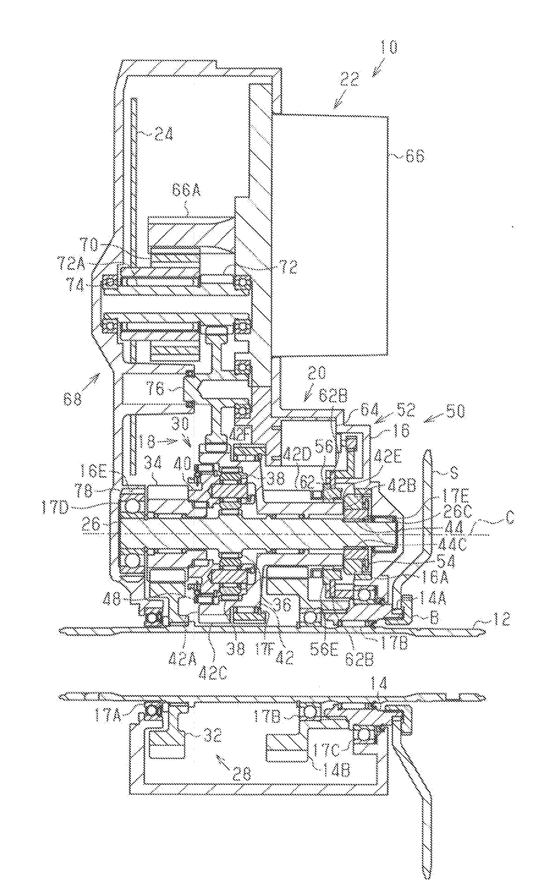
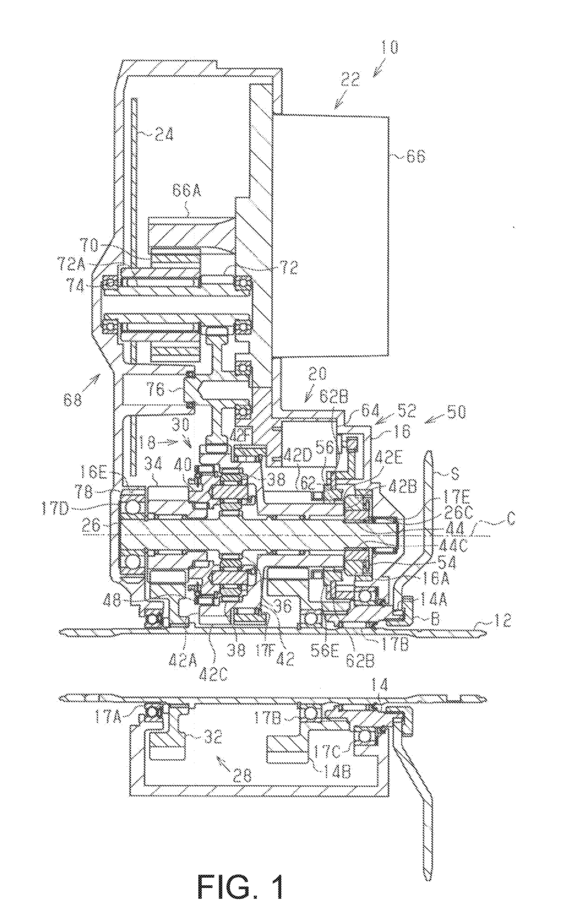
[0110]As shown in FIG. 14, the bicycle drive unit 10 comprises the input rotational shaft 12, the output part 14, the housing 16, the assist mechanism 22, a transmission mechanism 80 and a switching mechanism 82.

[0111]The transmission mechanism 80 comprises a transmission shaft 84, a transmission body 86, a first rotating body 88, a second rotating body 90, a third rotating body 92 and a fourth rotating body 94.

[0112]The transmission shaft 84 is disposed outside of the input rotational shaft 12 in the radial direction. The transmission shaft 84 is provided parallel to the input rotational shaft 12. The transmission shaft 84 is rotatably supported by the housing 16. The transmissi...

modified example

[0136]The specific form that the bicycle drive unit can take is not limited to the forms illustrated in the above-described embodiments. The bicycle drive unit can take various forms different from the above-described embodiments. The modified examples of the above-described embodiments discussed below are examples of the various forms that the bicycle drive unit can take.

[0137]The assist motor 66 of the first embodiment can be connected to the carrier 40 or the input rotational shaft 12 via the decelerating mechanism 68. In short, the torque of the motor 66 may be transmitted to any rotating body, as long as the rotating body is upstream from the ring gear 42 to which the annular member 56 of the switching mechanism 20 is coupled, on the power transmission path from the input rotational shaft 12 to the output part 14.

[0138]The connecting part 50 of the first embodiment can be provided to the opposing portion 16A. in this case, the grooves 56B are formed on the outer periphery of th...


PUM


Abstract

A bicycle drive unit is basically provided with an input rotational shaft, an output part, a transmission mechanism, an assist motor and a switching mechanism. The transmission mechanism has at least two shift stages, and is configured to change a speed of a rotational input that is input from the input rotational shaft and output this rotational input to the output part. The assist motor is coupled to a power transmission path from the input rotational shaft to the output part, and is driven according to a manual drive force. The switching mechanism is configured to switch a gear changing state of the transmission mechanism by using a rotational force of the assist motor.

Description

CROSS-REFERENCE TO RELATED APPLICATIONS[0001]This application claims priority to Japanese Patent Application No. 2015-063155, filed on Mar. 25, 2015. The entire disclosure of Japanese Patent Application No. 2015-063155 is hereby incorporated herein by reference.BACKGROUND[0002]1. Field of the Invention[0003]This invention generally relates to a bicycle drive unit.[0004]2. Background Information[0005]A bicycle drive unit is described in Japanese Patent No. 5,523,636 that comprises a transmission mechanism that can reduce the speed of a rotation input to a crankshaft and output this rotation to an output part, as well as a switching mechanism for switching between a state in which the crankshaft and the output part are connected and a state in which the connection between the crankshaft and the output part is released. When the switching mechanism is in a state in which the crankshaft and the output part are released, the rotation that is input to the crankshaft is decelerated by the ...

Claims


Application Information

Patent Timeline
Patent Type & Authority Applications(United States)
IPC IPC(8): B62M11/14F16D41/24B62M6/40
CPCB62M6/40B62M11/14F16D41/24B62M6/55B62M11/145F16D41/30
Inventor YAMAMOTO, TAKASHIURABE, HIROYUKINISHIKAWA, YUSUKE
Owner SHIMANO INC
Why Eureka
Try Eureka