Supercharge Your Innovation With Domain-Expert AI Agents!

Box cutter structure

a box cutter and box cutter technology, applied in the field of cutting tools, can solve the problems of user accidental cutting, blade movement, blade not immediately re-entering the blade carrier,

Inactive Publication Date: 2016-10-06
HACKSAW & KNIFE MANUFACTORY
View PDF8 Cites 2 Cited by
  • Summary
  • Abstract
  • Description
  • Claims
  • Application Information

AI Technical Summary

Benefits of technology

The invention is a box cutter that automatically retracts its blade after it has been pushed and disarmed, to prevent the user from being cut.

Problems solved by technology

However, in this conventional structure, the user has to push and pull the controller by finger when using the box cutter.
Moreover, the controller is an integrally formed member, and the blade is assembled on the controller; therefore, once the controller and the position-restricting structure are not stuck with each other, the blade is movable, and the user may be cut accidentally.
It is dangerous that the blade does not retreat into the blade carrier immediately.

Method used


Image

  • Box cutter structure
  • Box cutter structure
  • Box cutter structure

Examples


Embodiment Construction

[0021]The present invention will be clearer from the following description when viewed together with the accompanying drawings, which show, for purpose of illustrations only, the preferred embodiment in accordance with the present invention.

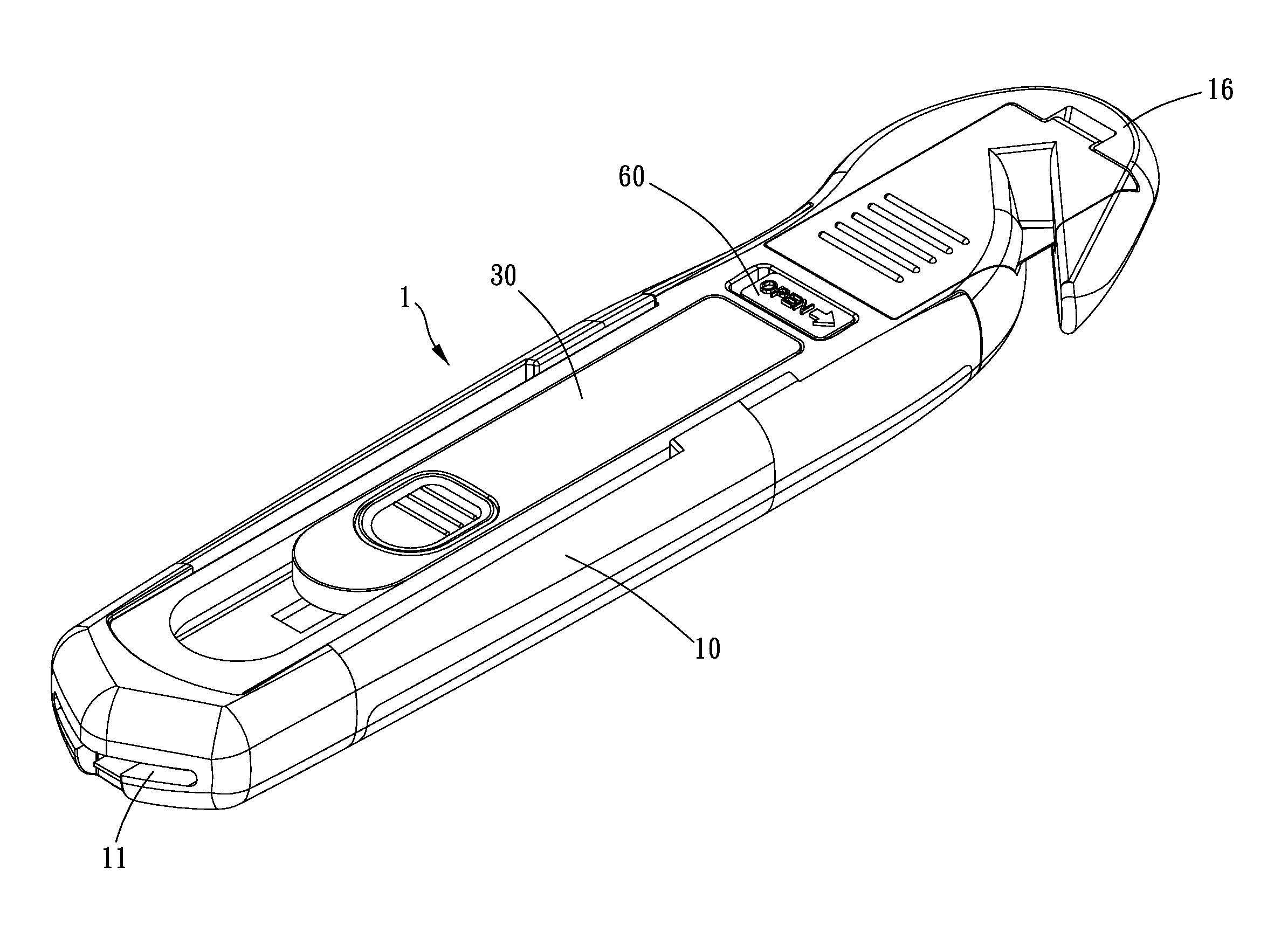
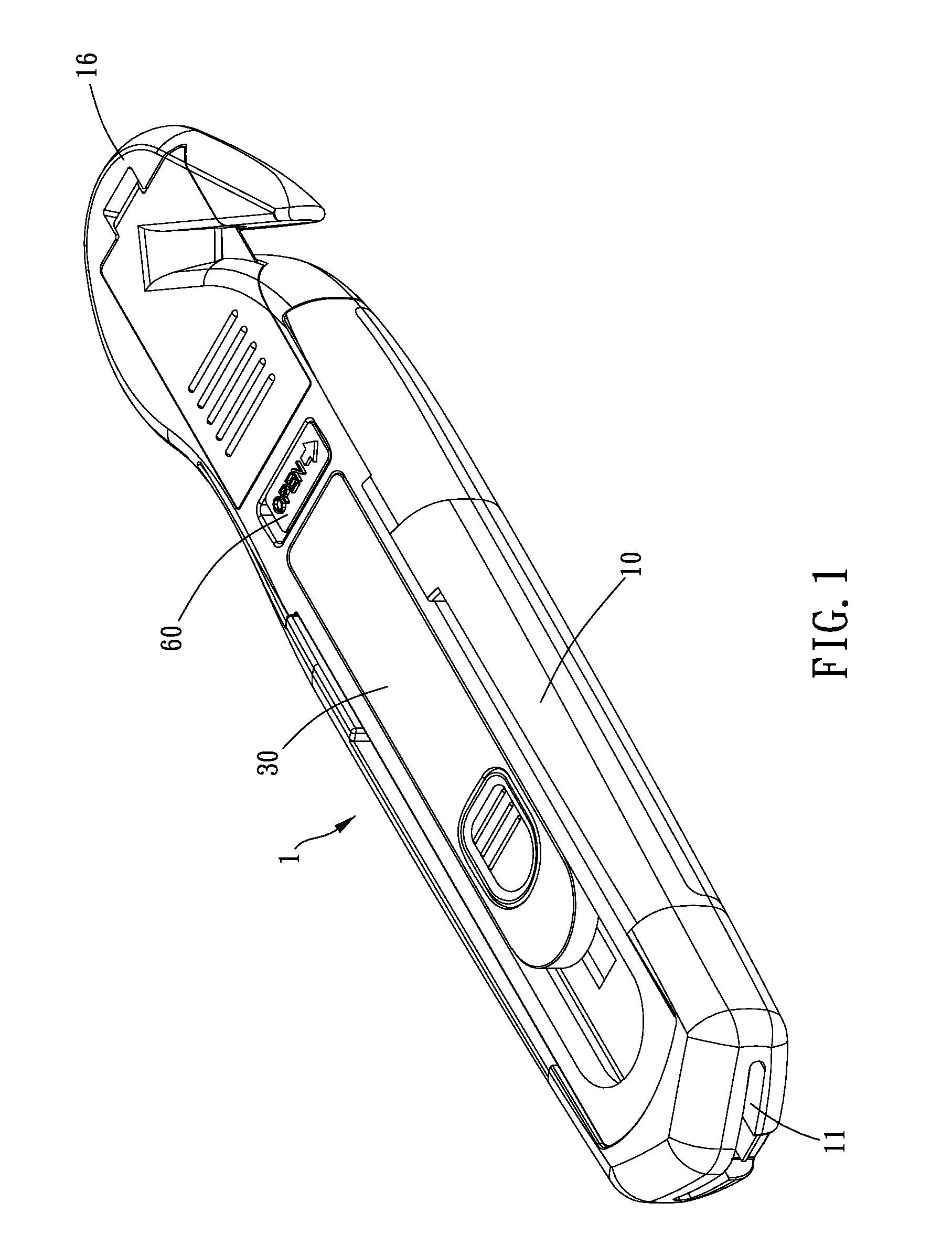
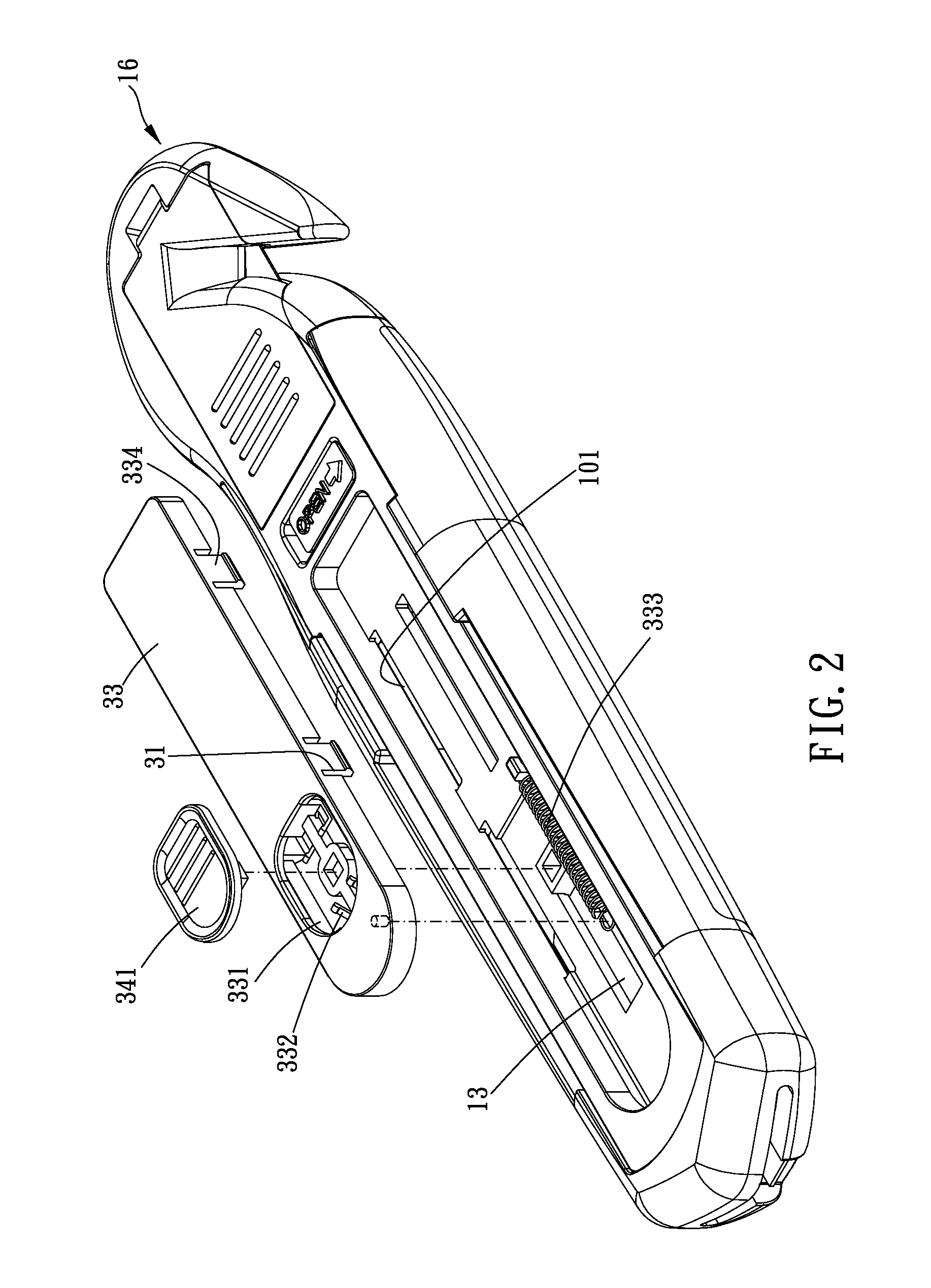
[0022]Please refer to FIGS. 1 to 8 for a preferred embodiment of a box cutter structure 1 of the present invention. The box cutter structure 1 includes a shell 10, a blade carrier 20 and a pushing assembly 30.

[0023]The shell 10 has a blade-projecting end 11 and a restriction portion 12. Specifically, the shell 10 is protrudingly formed with the restriction portion 12 on an inner face thereof and penetratingly formed with at least one guiding slot 13.

[0024]The blade carrier 20 is slidably disposed in the shell 10 and provided for carrying a blade 40. The blade carrier 20 further has a pushed portion 21. Specifically, each of two sides of the blade carrier 20 in a width direction is formed with a channel 22, and a wall of the channel 22 forms the p...


PUM


Abstract

A box cutter structure is provided, including a shell, having a blade-projecting end and a restriction portion; a blade carrier, slidably disposed in the shell for carrying a blade, having a pushed portion; a pushing assembly, disposed on the shell, being operable from outside the shell to move between a locking position and a releasing position, having an pushing portion and a blocking portion; wherein, when the pushing assembly is in the locking position, the restriction portion blocks a path along which the blocking portion moves toward the blade-projecting end, and the blade is unprojectable out of the blade-projecting end; when the pushing assembly is in the releasing position, the restriction portion is not on a path along which the blocking portion moves toward the blade-projecting end, and the blade is projectable out of the blade-projecting end.

Description

BACKGROUND OF THE INVENTION[0001]1. Field of the Invention[0002]The present invention relates to a cutting tool, and more particularly to a box cutter structure.[0003]2. Description of the Prior Art[0004]Usually, a box cutter is light, sharp and convenient to cut objects, and the box cutter is widely used. The conventional box cutter generally includes a long blade carrier, a blade disposed on the blade carrier and a controller which can be pushed and pulled by a user's finger. Through the user's finger pushing or pulling the controller, the controller controls the blade to move forward or backward inside the blade carrier; that is, the blade can be moved forward to project an edge out of the blade carrier, or the blade can be moved backward to retreat back to the blade carrier. The above-mentioned structure is disclosed in TWM 487191 and TWM 435984.[0005]However, in this conventional structure, the user has to push and pull the controller by finger when using the box cutter. In add...

Claims


Application Information

Patent Timeline
Patent Type & Authority Applications(United States)
IPC IPC(8): B26B1/08
CPCB26B1/08
Inventor HUANG, YIN-HANHUANG, TIEN-YU
Owner HACKSAW & KNIFE MANUFACTORY
Features
  • R&D
  • Intellectual Property
  • Life Sciences
  • Materials
  • Tech Scout
  • Unparalleled Data Quality
  • Higher Quality Content
  • 60% Fewer Hallucinations
Learn More