Automatically setting window width/level based on referenced image context in radiology report

a technology of automatic setting and window width, applied in the field of automatic setting window width/level based on referenced image context in radiology report, can solve problems such as quality compromis

Pending Publication Date: 2016-10-06
KONINKLJIJKE PHILIPS NV
View PDF11 Cites 24 Cited by
  • Summary
  • Abstract
  • Description
  • Claims
  • Application Information

AI Technical Summary

Problems solved by technology

Manually setting each image view context is a time consuming and inefficient process which may prevent users from navigating to referenced images, resulting in a possible compromise in quality.

Method used


Image

  • Automatically setting window width/level based on referenced image context in radiology report
  • Automatically setting window width/level based on referenced image context in radiology report
  • Automatically setting window width/level based on referenced image context in radiology report

Examples


Embodiment Construction

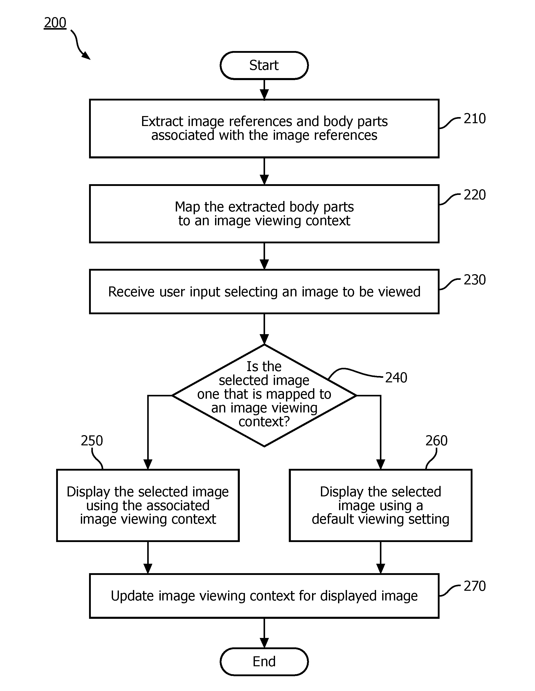
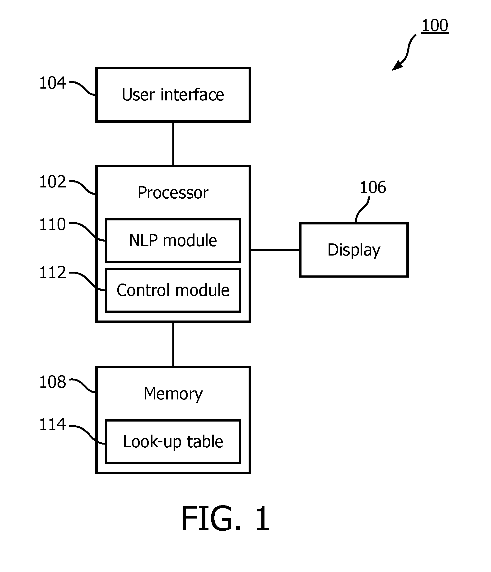
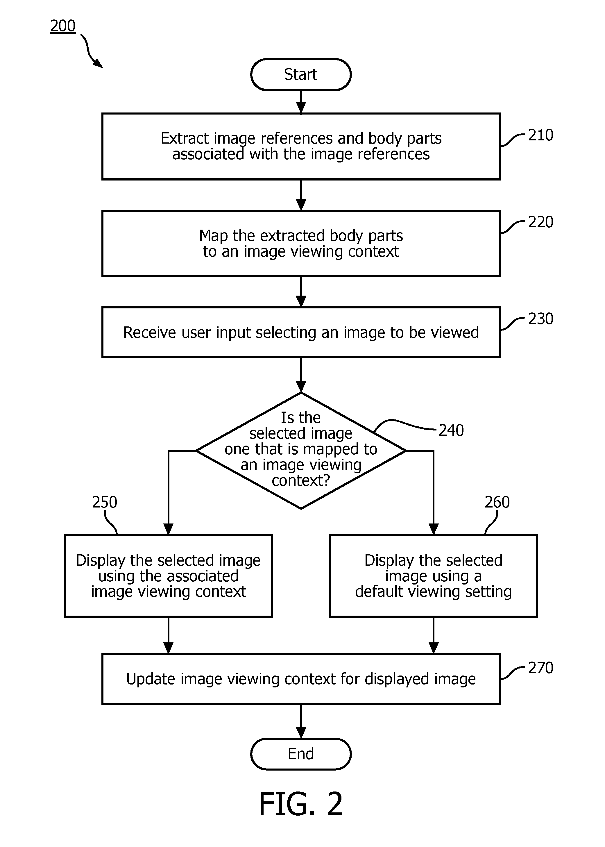
[0008]The exemplary embodiments may be further understood with reference to the following description and the appended drawings, wherein like elements are referred to with the same reference numerals. The exemplary embodiments relate to a system and method for reviewing a medical image. In particular, the exemplary embodiments describe a system and method for extracting imaging context information from free-text radiology reports and applying the imaging context information to an associated image so that a user is not required to manually set the image viewing context (e.g., a window width / level in which the associated image is to be viewed). Automatically setting image viewing context based on extracted information facilitates workflow automation and eliminates unnecessary trivial tasks currently performed by the radiologist. Although the exemplary embodiments are specifically described in regard to reviewing images of cancer patients within a radiology department, it will be under...


PUM


Abstract

A system and method for automatically setting image viewing context. The system and method perform the steps of extracting image references and body parts associated with the image references from a report, mapping each of the body parts to an image viewing context so that image references associated are also associated with the image viewing context, receiving a user selection indicating an image to be viewed, determining whether the user selection is one of the image references associated with the image viewing context and displaying the image of the user selection

Description

BACKGROUND[0001]Radiologists must routinely work with an increasing number of studies to diagnose and treat patients in an optimal manner. Patients, especially ones with cancers, frequently undergo imaging exams and over time accumulate many studies and reports in their medical records. Each time a new study needs to be read, the radiologist would typically open one or more prior reports to understand the status of the patient's findings and establish clinical context. Oftentimes, in the report text, the findings are associated with reference to images along with the body part or anatomy in which the finding is located. The report may include text such as, for example, “partially calcified right heart border reference lesion measures 2.4×1.6 cm (series 11 image 65).” Generally, findings on the image references are best viewed in a setting corresponding to the anatomy. According to the above example, the findings in the referenced image may best be viewed in the image setting for win...

Claims


Application Information

Patent Timeline
Patent Type & Authority Applications(United States)
IPC IPC(8): G06F19/00G06K9/00G06F17/30G16H10/60G16H30/40G16H70/60
CPCG06F17/30528G06F17/30994G06K9/00463G06F17/3028G06F19/326G06F19/3443G06F19/321G16H50/70G06F16/51G06F16/904G06F16/24575G16H30/40G16H70/60G16Z99/00G06V30/414
Inventor TELLIS, RANJITH NAVEENMAGOTUWANA, THUSITHA DANANJAYA DE SILVAQIAN, YUECHEN
Owner KONINKLJIJKE PHILIPS NV
Why Eureka
Try Eureka