
Terminal device

Inactive Publication Date: 2016-10-13
JO HEE CHUL
View PDF0 Cites 0 Cited by
  • Summary
  • Abstract
  • Description
  • Claims
  • Application Information

AI Technical Summary

Benefits of technology

The present invention is a terminal device that allows for the creation of an additional terminal even when there is no way to charge it. This means that users can use various additional terminals, such as a portable multimedia device and a battery, when they need to connect to an outside device. The terminal device is designed to be useful in various fields and can be utilized with different types of external devices.

Problems solved by technology

To this end, a terminal is used provided by a smart phone, which however generates lots of restrictions.

Method used


Image

  • Terminal device
  • Terminal device
  • Terminal device

Examples


Embodiment Construction

[0019]Now, the present invention will be described in detail with reference to the accompanying drawings. In the drawings, the size and relative sizes of layers, regions and / or other elements may be exaggerated or reduced for clarity.

[0020]Accordingly, the meaning of specific terms or words used in the specification and claims should not be limited to the literal or commonly employed sense, but should be construed or may be different in accordance with the intention of a user or an operator and customary usages. Therefore, the definition of the specific terms or words should be based on the contents across the specification.

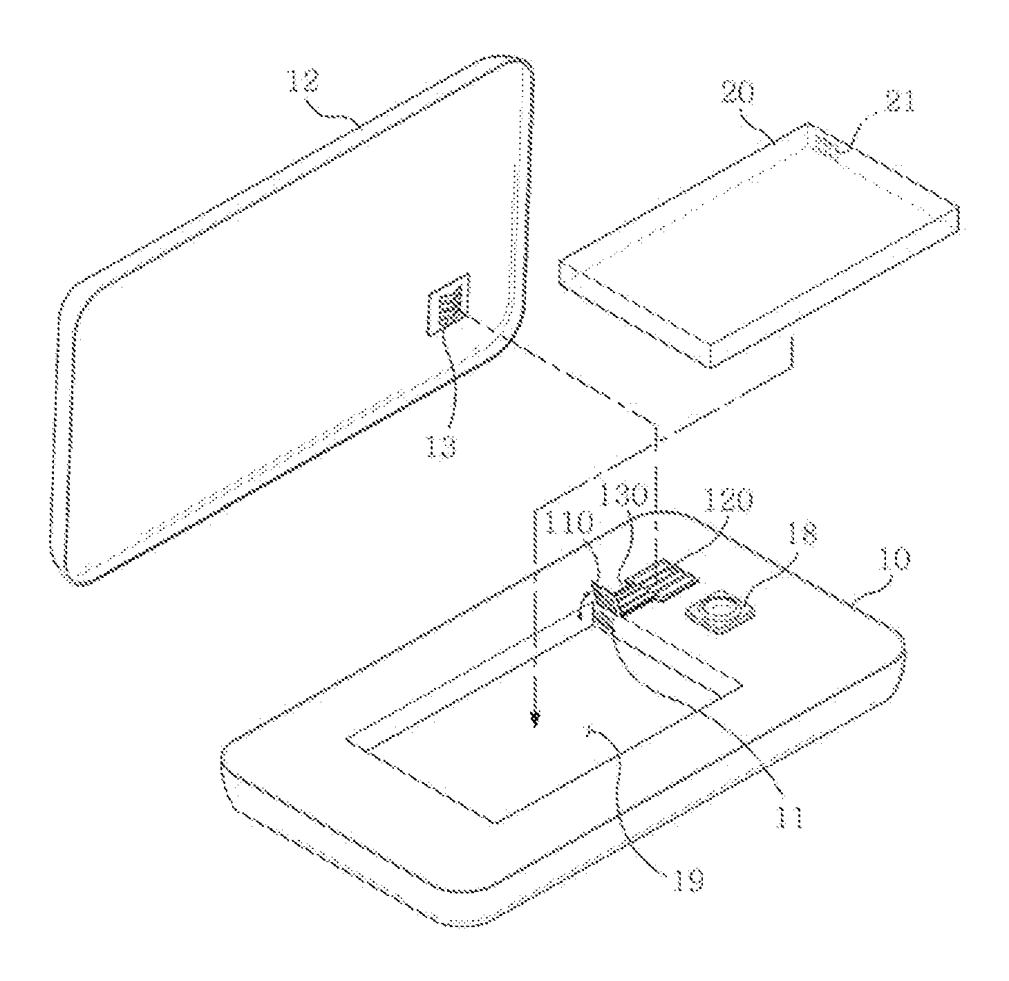
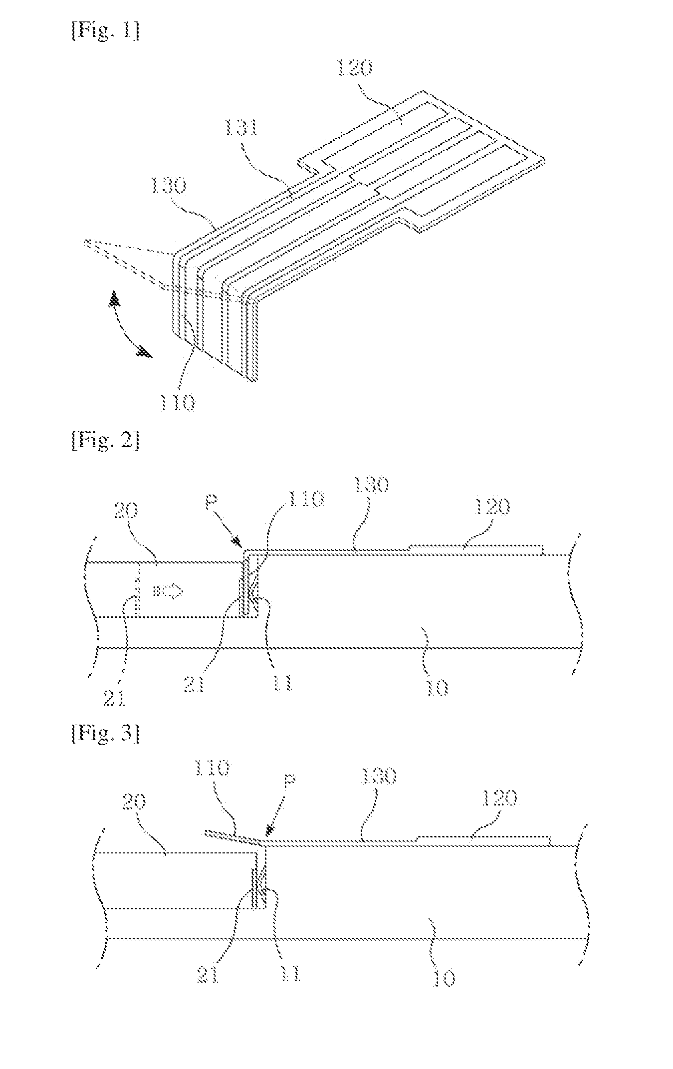
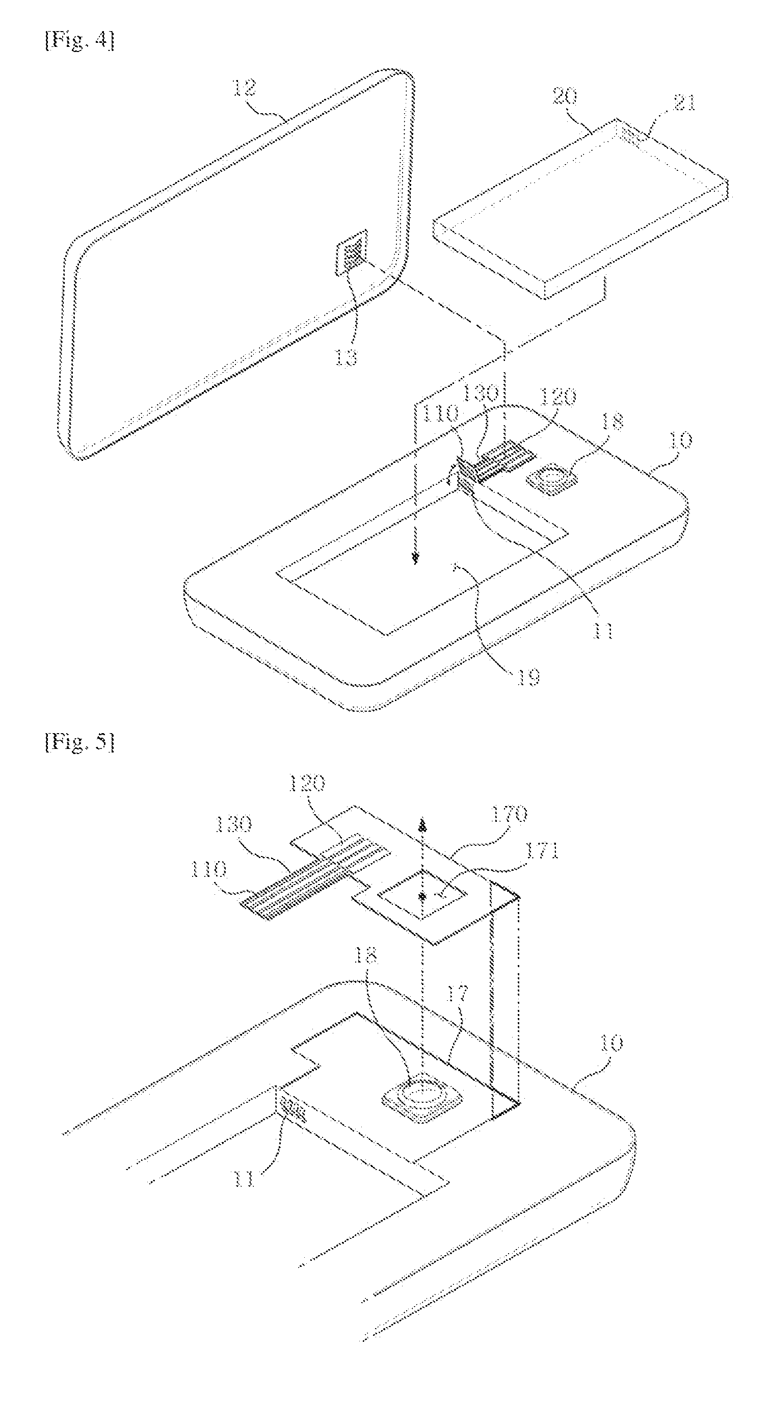
[0021]FIG. 1 is a block diagram illustrating a terminal device according to the present invention. The terminal device illustrated in FIG. 1 may include a first terminal (110) and a substrate (130) mounted with a second terminal (120). The first terminal (110) may be interposed between mutually contacted first outside terminal (11) and second outside terminal (21...


PUM


Abstract

The present invention relates to a terminal device, the terminal device including a first terminal, and a substrate mounted with a second terminal electrically connected to the first terminal, wherein the first terminal is interposed between mutually contacted first and second outside terminals, and is electrically connected to the first outside terminal or the second outside terminal.

Description

TECHNICAL FIELD[0001]The teachings in accordance with the exemplary embodiments of this invention relate generally to a terminal device, and more particularly to a terminal device by which a portable multimedia device can be charged.BACKGROUND ART[0002]Various smart phone peripheral devices are provided concomitant with fast propagation of smart phones. Hereinafter, smart phones are used to commonly refer to all types of portable multimedia devices. Some of the peripheral devices require an electrical connection with a smart phone or a battery. To this end, a terminal is used provided by a smart phone, which however generates lots of restrictions.[0003]Although Korea Laid-Open Patent No.: 10-2013-0107426 discloses a technology teaching a quick recharge of a smart phone, a terminal provided by the smart phone is used as it is without any change.DISCLOSURE OF INVENTIONTechnical Problem[0004]The present invention is directed to solve at least one or more of the aforementioned disadvant...

Claims


Application Information

Patent Timeline
IPC IPC(8): H04M1/02H01R12/77H01R13/631H01R13/24
CPCH04M1/0274H01R13/24H04M1/0262H01R13/631H01R12/77H04M1/0264H04M1/0277H01R12/55H01R12/51
Inventor JO, HEE-CHUL
Owner JO HEE CHUL
Learn More