Image forming system, image forming method and information terminal device

a technology of image forming and information terminal, which is applied in the direction of visual presentation using printers, digital output to print units, instruments, etc., can solve the problems of reducing processing speed, working efficiency drop, and needing administrator registration

Inactive Publication Date: 2011-01-11
FUJIFILM BUSINESS INNOVATION CORP
View PDF27 Cites 250 Cited by
  • Summary
  • Abstract
  • Description
  • Claims
  • Application Information

AI Technical Summary

Problems solved by technology

Therefore, the data communications between the electronic equipment having plural communication means have a disadvantage that the working efficiency drops because a connection process is executed by each of the communication means and a data format according to the specifications of each communication means must be used.
In order to have the electronic equipment, which is recognized as different electronic equipment by the individual communication means, recognized as one and the same, there are problems that registration by an administrator is required and re-registration must be made every time there is a change.
But, the related art described in Japanese Patent Application Laid-Open No. 2000-349803 has problems that a storage area for storing the IP address management table is required, a larger storage area is required as the controlled product increases, and the storage region is cluttered, resulting in decreasing the processing speed because the controlled product which cannot be connected directly to the Internet and the IP address of the controlled product must be registered in the IP address management table.
There are also problems that the gateway device is required to realize communications, and when it is desired to connect to a single controlled product, not only convenience cannot be enjoyed but it is necessary to maintain the management table and the network, and productivity is disturbed.
But, this communication method has problems that because the electronic equipment connected as described above is recognized as different electronic equipment by the individual communication means, a registration operation by an administrator is required to have the electronic equipment, which is judged different by the individual communication means, recognized as one and the same in order to realize seamless communications beyond the constraints of the communication means, and the working efficiency is degraded.

Method used


Image

  • Image forming system, image forming method and information terminal device
  • Image forming system, image forming method and information terminal device
  • Image forming system, image forming method and information terminal device

Examples


Embodiment Construction

[0024]An embodiment of an image forming system, an image forming method and an information terminal device according to the present invention will be described in detail with reference to the accompanying drawings.

[0025]It should be noted that, as an information terminal device, there are available various devices such as personal computers (PCs), etc.; however, the following embodiment will be described with reference to an image reading device as an example of the information reading device. Moreover, the image forming system of the present invention will be described with reference to a scanner for reading images and a printer for printing but is not limited to this example and can be used for communications between peripheral equipment such as a digital camera or a PDA (Personal Digital Assistance) and a printer and communications between a server and peripheral equipment.

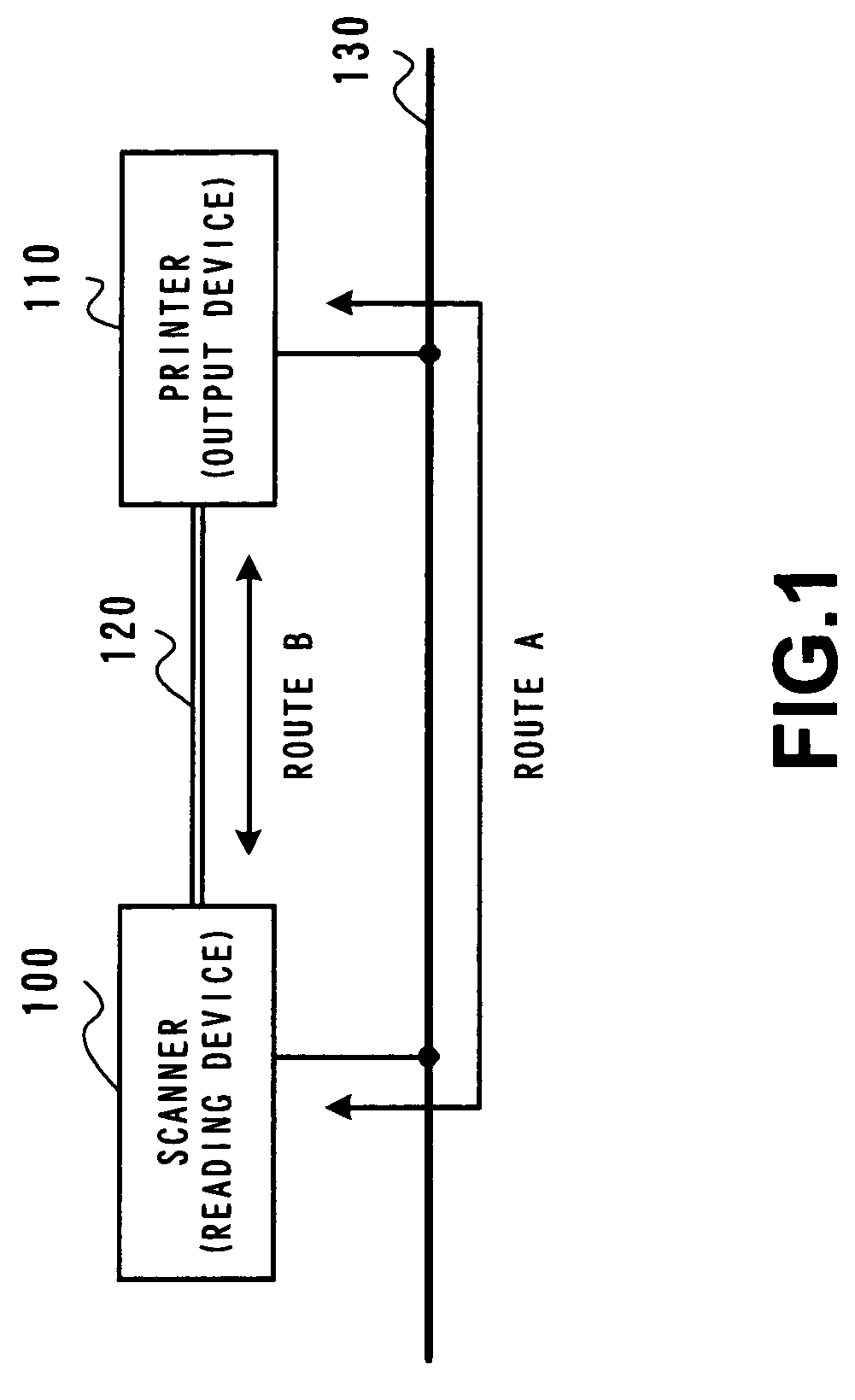
[0026]FIG. 1 is a system configuration view of the image forming system configured by applying the image for...


PUM


Abstract

An image forming system comprising an information terminal device and a printing device that is connected to the information terminal device through a network and a local connection and performs a printing process of image data sent from the information terminal device, in which the information terminal device includes a network identifier acquisition unit that obtains through the local connection a network identifier of the printing device on the network at the time of the local connection between the information terminal device and the printing device, and a data communication unit that performs data communications with the printing device through the network according to the network identifier obtained by the network identifier acquisition unit.

Description

BACKGROUND OF THE INVENTION[0001]1. Field of the Invention[0002]The present invention relates to an image forming system, an image forming method and an information terminal device in which data communications are made between electronic equipment which are mutually connected through plural communication lines, and more particularly to an image forming system, an image forming method and an information terminal device in which mutual communications between electronic equipment can be performed by using information obtained through each communication line for data communications using another communication line.[0003]2. Description of the Related Art[0004]There have been developed various connection methods as communication means between electronic equipment in these years, and their typical examples include a network connection that realizes data communications by handling plural devices as nodes on a network and a P2P (Peer to Peer) connection that directly connects electronic equi...

Claims


Application Information

Patent Timeline
Patent Type & Authority Patents(United States)
IPC IPC(8): G06F3/12
CPCH04N1/00278H04N1/32797H04N2201/0015H04N2201/0039H04N2201/0041H04N2201/0049H04N2201/0081
Inventor OSHIMA, AKIHIDE
Owner FUJIFILM BUSINESS INNOVATION CORP
Why Eureka
Try Eureka