Method for Testing for Fluid Leaks

a fluid leakage and testing method technology, applied in the direction of survey, instruments, borehole/well accessories, etc., can solve the problems of widely accepted leakage rate measurement using indirect result of pressure decay, and achieve the effect of reducing the time period for measuring the amount of intensifying fluid loss and reducing costs

Active Publication Date: 2016-10-27
ENGIP LLC
View PDF1 Cites 1 Cited by
  • Summary
  • Abstract
  • Description
  • Claims
  • Application Information

AI Technical Summary

Benefits of technology

[0009]In the initial phase of pressurization, an Apparent Compressibility Factor (ACF) is determined as discussed below. When the BOP or fluid system is at the test pressure, the amount of intensifying fluid needed to maintain the system at test pressure is measured over a time period and recorded. The psi / min decay rate based upon the ACF and the measured volume loss per time is then determined as discussed below. This decay rate is compared to the acceptable decay rate to see if the BOP or system passed the test. The time period for measuring the amount of intensifying fluid loss can be significantly lowered by using the ACF measurement which results in a considerable reduction in costs associated with the test.

Problems solved by technology

Measuring leak rate utilizing the indirect result of pressure decay, while widely accepted, is problematic and not indicative of a specific leak rate.

Method used


Image

  • Method for Testing for Fluid Leaks

Examples


Embodiment Construction

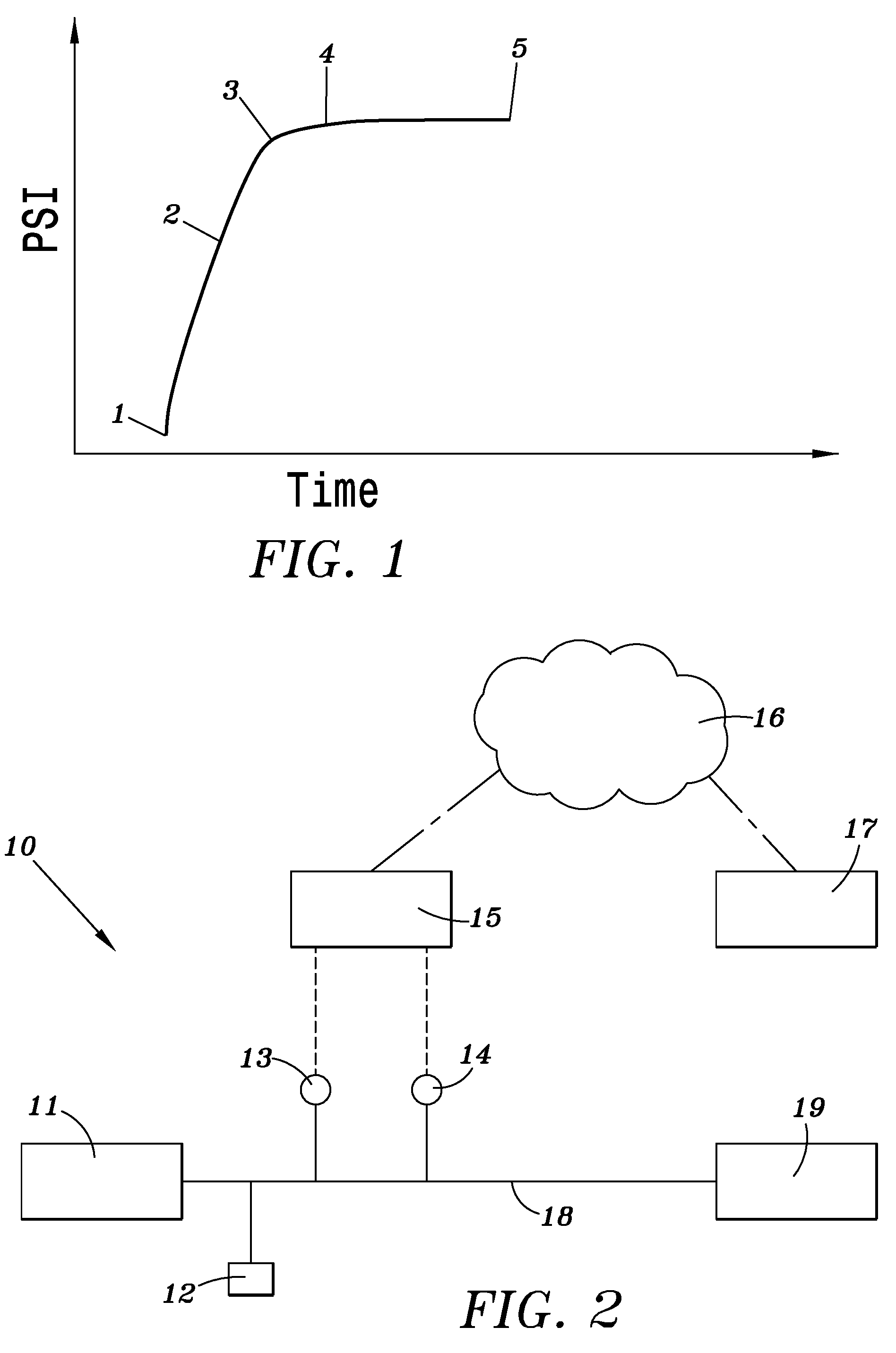
[0013]FIGS. 1 and 2 illustrates an embodiment of the test cycle. The pressure in the BOP or system 19 which may contain trapped air is raised from point 1 to point 4 as shown in FIG. 1. Point 4 represents the test pressure level. As the test pressure increases from point 3 to point 4, the incremental pressure change of the intensifying pressure is measured by a pressure sensor 13 and the incremental volume change of intensifying fluid is also monitored by a volume meter 14 positioned in flow conduit 18 which leads to BOP or system 19. During a typical test cycle an isolated area of the BOP which may include valves and safety devices is pressurized and volume rates and pressure of the intensifying fluid are recorded by the sensors 13 and 14. Thus information is sent to a computer processor 15.

[0014]The Apparent Compressibility Factor ACF is calculated by the following formula.

Va / PSIA=ACF

[0015]Where Va=Incremental volume change of intensifying fluid, PSIA=Incremental pressure change o...


PUM


Abstract

Blowout preventers, fluid pressure systems and portions thereof may be tested for leaks by calculating an Apparent Compressibility Factor which is determined during initial pressurization of the system to the test pressure. The equivalent decay rate is calculated by measuring the amount of intensifying fluid required to be added to maintain the system at the test pressure level. The equivalent decay rate in psi per minute is then compared to the acceptable decay rate for the pressure level of the test to determine if the system passed the test.

Description

CROSS-REFERENCE TO RELATED APPLICATIONS[0001]This application claims priority to U.S. provisional application 62 / 191,419 filed Jul. 12, 2015 and is a continuation in part of U.S. application Ser. No. 15 / 151,323 filed May 10, 2016 which claims priority to provisional application 62 / 159,429 filed May 11, 2015. This application is also a continuation in part of application Ser. No. 14 / 932,727 filed Nov. 4, 2015 which claims priority to provisional application 62 / 140,795 filed Mar. 31, 2015.[0002]The entire contents of the above identified provisional and non-provisional U.S. patent applications are expressly incorporated herein reference thereto.BACKGROUND OF THE INVENTION[0003]1. Field of the Invention[0004]This application is directed to a method of testing a closed hydraulic system for example a blowout preventer (BOP) assembly for leaks. Oil and Gas Exploration risk management includes the ability to control subsurface pressure which may be encounted during drilling operation. The ...

Claims


Application Information

Patent Timeline
Patent Type & Authority Applications(United States)
IPC IPC(8): G01M3/28E21B33/06E21B47/10
CPCG01M3/2876E21B33/06E21B47/1025E21B47/117G01M3/28G01M3/26G01M3/2815
Inventor HILPERT, CLIFFORD LEEHILPERT, JEFFERY
Owner ENGIP LLC
Why Eureka
Try Eureka