Key switch structure

Active Publication Date: 2016-11-17
FANUC LTD
View PDF4 Cites 0 Cited by
  • Summary
  • Abstract
  • Description
  • Claims
  • Application Information

AI Technical Summary

Benefits of technology

The invention improves the appearance of keys by guiding them to the center position of the keyhole using a matching shape on the key sheet. This prevents the key top from getting caught when pressed and ensures a smooth operation.

Problems solved by technology

Further, a problem easily occurs that the key top 2 is caught by the edge of the keyhole 11 in the case body 1 when its corner is pressed.
In the positioning techniques as described in the above patent documents, however, a special mechanism is needed to align the center position of the key top with the center position of the keyhole, so that there are problems of increased manufacturing costs and time-consuming assembly.

Method used


Image

  • Key switch structure
  • Key switch structure
  • Key switch structure

Examples


Embodiment Construction

[0020]According to the present invention, the above-described problems are solved by machining a part of a key sheet that constitutes a key switch structure, which touches a pressing protuberance of a key top, into an emboss shape.

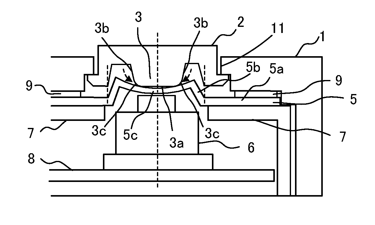
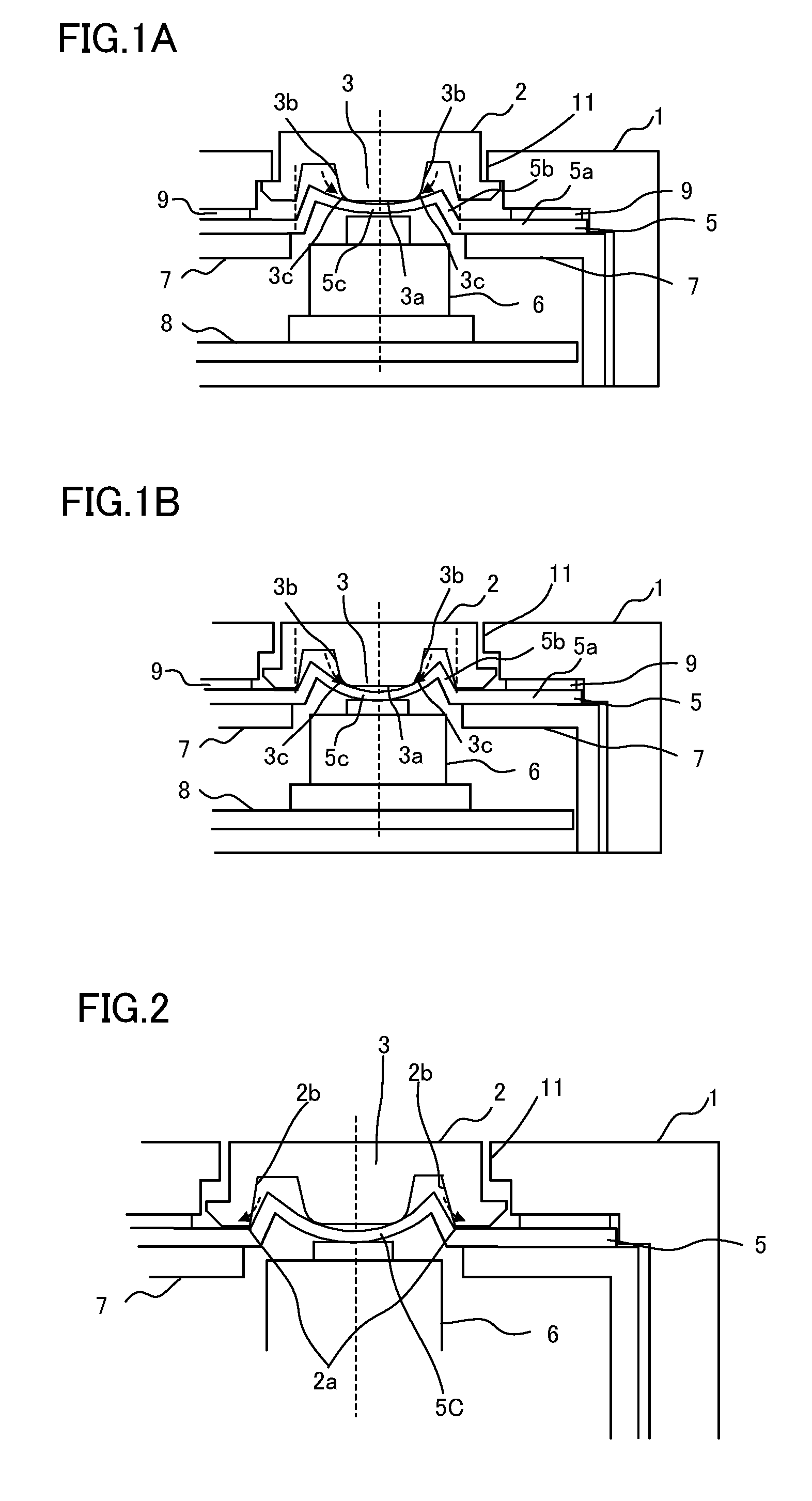
[0021]FIGS. 1A and 1B are sectional views of a key switch structure according to one embodiment of the present invention.

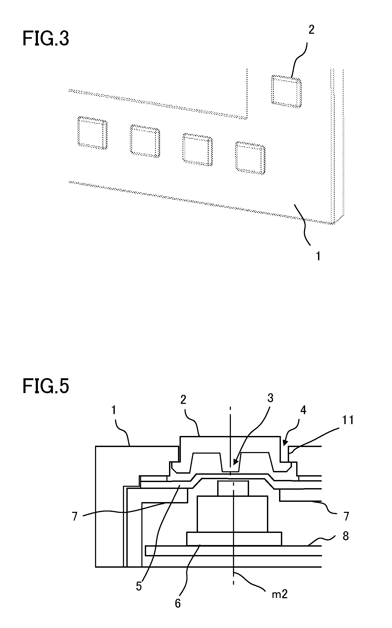
[0022]This key switch structure mainly comprises a key top 2 with a pressing protuberance 3, a key sheet 5 supported on a key sheet reinforcement plate 7, and a key switch 6 mounted on a key base 8.

[0023]The pressing protuberance 3 of the key top 2 comprises a tip portion 3a, side portions 3b, and tip corner parts 3c. The tip portion 3a is configured to press the key switch 6 through the key sheet 5 when the key top 2 is depressed. The tip corner parts 3c are boundaries between the tip portion 3a and the side portions 3b.

[0024]Further, the key sheet 5 comprises a flat portion 5a, which serves as a base of the key sheet, and a wall porti...


PUM


Abstract

A key switch structure is provided with a key switch located in a position corresponding to a keyhole, a key top, and a key sheet disposed between the key switch and the key top. An embossed portion recessed inwardly relative to a case body is formed on the key sheet in a state where the key sheet is pressed down by a pressing protuberance of the key top not depressed, and tip corner parts of the pressing protuberance contact the formed embossed portion. Thus, the key top can be naturally positioned in the center position of the keyhole.

Description

BACKGROUND OF THE INVENTION[0001]1. Field of the Invention[0002]The present invention relates to a key switch structure.[0003]2. Description of the Related Art[0004]FIG. 5 is a view showing a conventional key switch structure.[0005]In the key switch structure, a control panel comprising a key top 2 with a pressing protuberance 3, a key sheet 5 supported on a key sheet reinforcement plate 7, and a key switch 6 mounted on a key base 8 is disposed in a case body 1. If the center position of the key top 2 is not aligned with the center position of a keyhole 11 in the case body 1 of the key switch structure of this type, as shown in FIG. 5, a gap between the key top 2 and the inner wall surface of the keyhole 11 is not uniform throughout the circumference of the key top 2, so that the external appearance is poor. Further, a problem easily occurs that the key top 2 is caught by the edge of the keyhole 11 in the case body 1 when its corner is pressed.[0006]Thus, it is advisable that the ke...

Claims


Application Information

Patent Timeline
IPC IPC(8): H01H13/04
CPCH01H13/04
Inventor HIRANO, KAZUHIKO
Owner FANUC LTD
Why Eureka
Try Eureka