Seat heating device and vehicle with same
- Summary
- Abstract
- Description
- Claims
- Application Information
AI Technical Summary
Benefits of technology
Problems solved by technology
Method used
Image
Examples
first exemplary embodiment
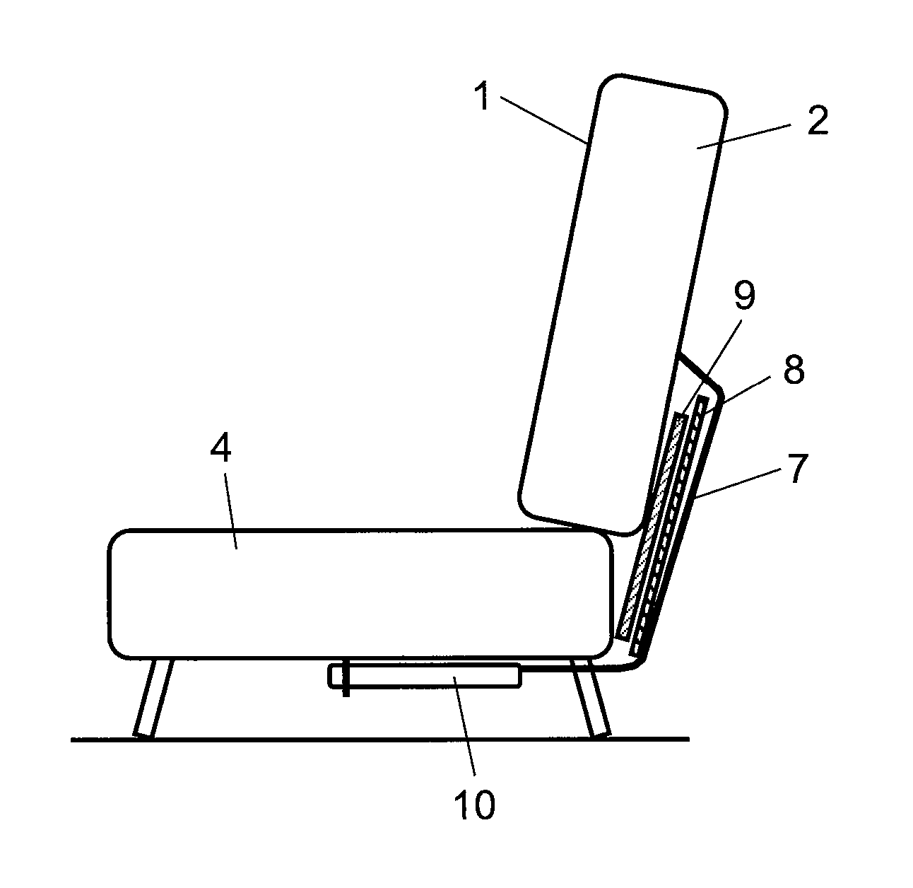
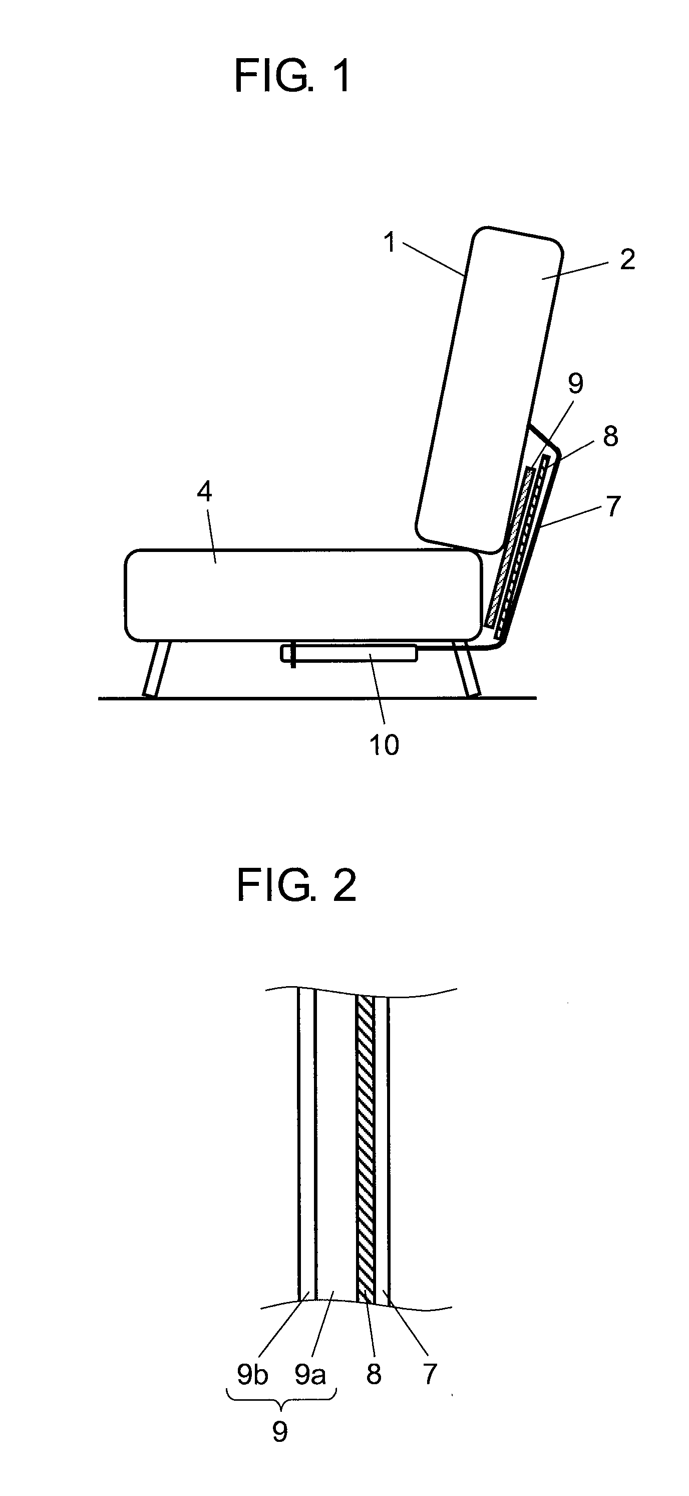
[0018]FIG. 1 is a cross sectional view of a seat installing a seat heating device in accordance with a first exemplary embodiment of the present invention.
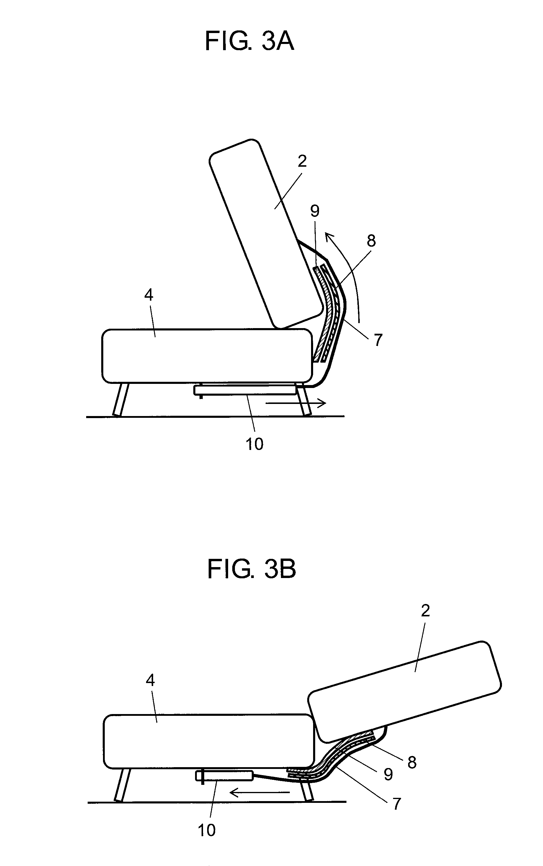
[0019]As is shown in FIG. 1, the seat heating device is composed of seat 1 composed of seat back 2 and seat part 4, heater 8 placed on a rear side of seat back 2 (an opposite side to sitting direction in seat 1) through a bottom side of seat part 4, cover 7, heat insulator 9, and elastic member 10. An end of cover 7 is attached to a cover cloth in a rear side of seat back 2 and an other end of which is attached to a bottom of seat part 4 through elastic member 10, covering heater 8.
[0020]Elastic member 10 is made of a rubber string, for instance and is hooked to a bottom of seat part 4 or is hooked directly to a cushion spring at the bottom of seat part 4, fixing cover 7.
[0021]As described, in the seat heating device according to the exemplary embodiment of the present invention, heater 8 is disposed on the rear side of seat back ...
second exemplary embodiment
[0033]FIG. 4A is a perspective view of seat cover 11 of a seat heating device in accordance with a second exemplary embodiment of the present invention in which seat back 2 is not yet covered with cover 7. FIG. 4B is a perspective view of the seat back 2 of the seat heating device in accordance with the second exemplary embodiment of the present invention which is covered with cover 7. Here, a same reference mark used in the first exemplary embodiment is used as long as the constituent part is identical to the one in the first exemplary embodiment.
[0034]FIG. 4A shows that seat back 2 of the seat heating device is composed of seat cover 11, upper rear surface 11a, lower rear surface 11b, and fitting part 12a and 12b. Seat back 2 of the seat heating device according to the exemplary embodiment is manufactured with following procedure.
[0035]First, separate upper rear surface 11a and lower rear surface 11b at fitting part 12a and 12b, and cover a urethane pad (not illustrated) with seat...
third exemplary embodiment
[0037]FIG. 5A is a perspective view of cover 7 of the seat heating device in accordance with a third exemplary embodiment of the present invention. FIG. 5B is a cross section view of cover 7 of the seat heating device in accordance with the third exemplary embodiment of the present invention. For a constituent part, a same reference mark used in embodiment 1 is applied as long as the part is identical to the one in the first exemplary embodiment.
[0038]As shown in FIG. 5A, cover 7 of the seat heating device has opening 13, flexible radiant transmission part 14 is disposed thereon covering opening 13 at the least. As shown in FIG. 5B, heater 8 and heat insulator 9 are disposed on radiant transmission part 14, facing a rear side of seat back 2. Radiant transmission part 14 is formed with an open lattice.
[0039]With above configuration, radiation heat generated by heater 8 passes through the open lattice of radiant transmission part 14, not passing through cover 7 but irradiating a back ...
PUM
 Abstract
Description
Claims
Application Information
 - R&D
- Intellectual Property
- Life Sciences
- Materials
- Tech Scout
- Unparalleled Data Quality
- Higher Quality Content
- 60% Fewer Hallucinations
Browse by: Latest US Patents, China's latest patents, Technical Efficacy Thesaurus, Application Domain, Technology Topic, Popular Technical Reports.
© 2025 PatSnap. All rights reserved.Legal|Privacy policy|Modern Slavery Act Transparency Statement|Sitemap|About US| Contact US: help@patsnap.com


