Method and Apparatus for Increasing Current Capacity of a Distributed Drive System

Active Publication Date: 2016-11-17
ROCKWELL AUTOMATION TECH
View PDF5 Cites 4 Cited by
  • Summary
  • Abstract
  • Description
  • Claims
  • Application Information

AI Technical Summary

Benefits of technology

The patent describes an improved system for connecting a DC bus cable to a module in a distributed motor drive system. It also describes a way to reduce the unwanted harmonic current that results from inverter switching. The system includes a capacitance module that can be attached to remote motor drives. The module has a housing, two DC bus connectors, and a terminal block with wire terminals for connecting to the DC bus cable. The module also has intermediate bus bars and slots for inserting DC bus bars. This system provides a stable connection that can handle high current levels, and it also doubles the current capacity between the DC bus cable and the DC bus bars. Additionally, the patent describes an extension module that can be added to the system for increased current capacity. Overall, the system improves the efficiency and stability of the distributed motor drive system.

Problems solved by technology

However, shared DC bus systems have not been fully met without incurring various disadvantages.
However, as the wire gauge for the DC bus cable increases, the weight of the cable similarly increases and flexibility for routing is reduced.
The increased weight and reduced flexibility of the cable generates increased strain on the connector for the motor drive to which the DC bus cable is connected.
The physical limitations on connecting the DC bus cable to the motor drive may restrict the current rating for a shared DC bus and, therefore, restrict the number of motor drives that may be connected to the shared DC bus.
However, inductance in the DC bus cable isolates the motor drive from the capacitance in the rectifier module.
These undesirable current components limit the amplitude of desirable DC bus current that may be conducted on the DC bus cable without exceeding the current rating for the DC bus cable and will reduce the life of the capacitors connected to the DC bus, potentially resulting in premature failure of a motor drive.

Method used


Image

  • Method and Apparatus for Increasing Current Capacity of a Distributed Drive System
  • Method and Apparatus for Increasing Current Capacity of a Distributed Drive System
  • Method and Apparatus for Increasing Current Capacity of a Distributed Drive System

Examples


Embodiment Construction

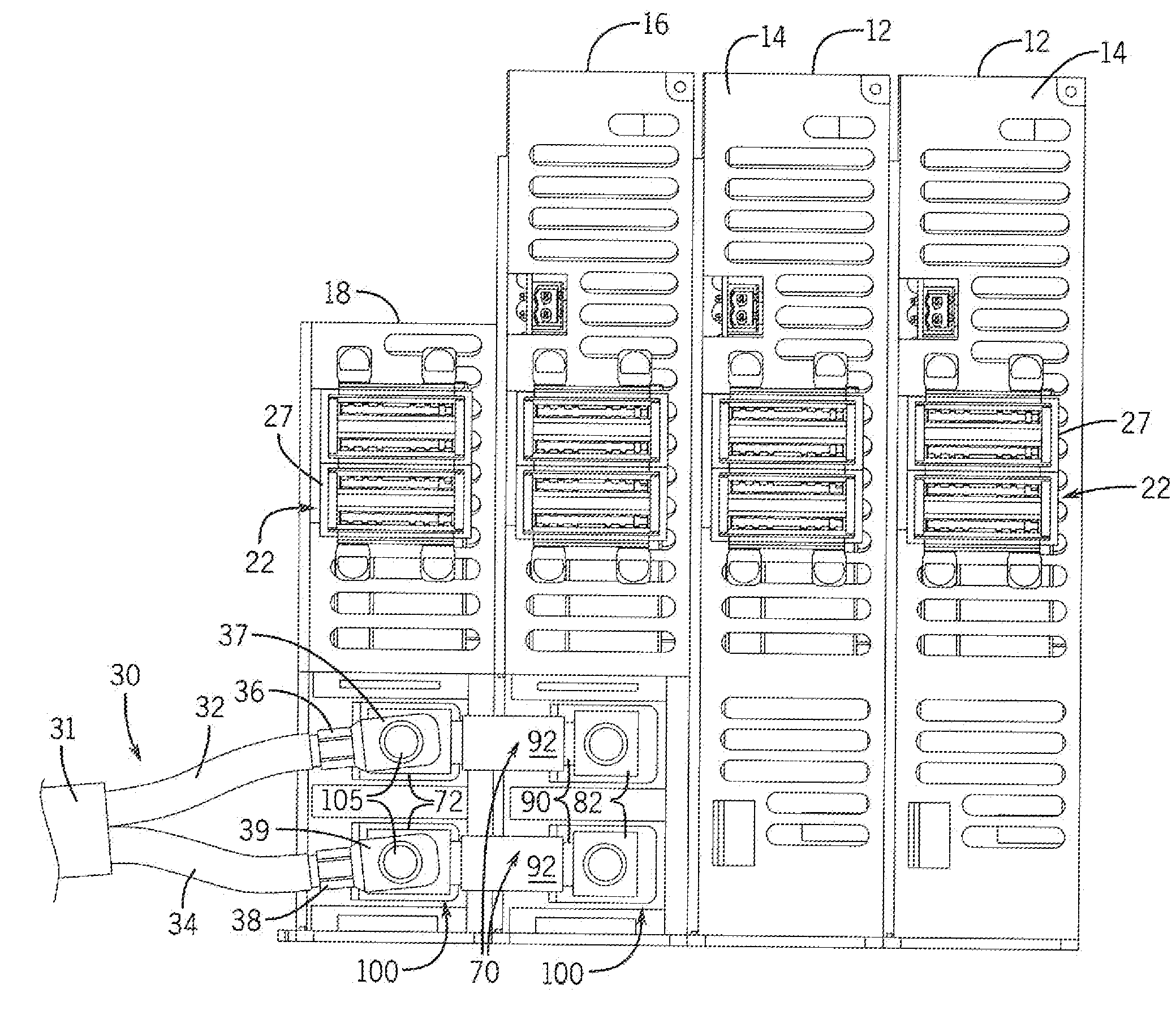
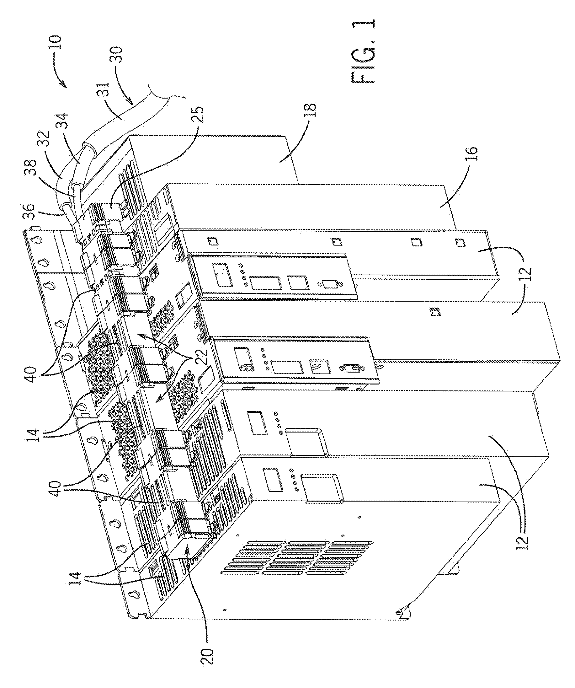
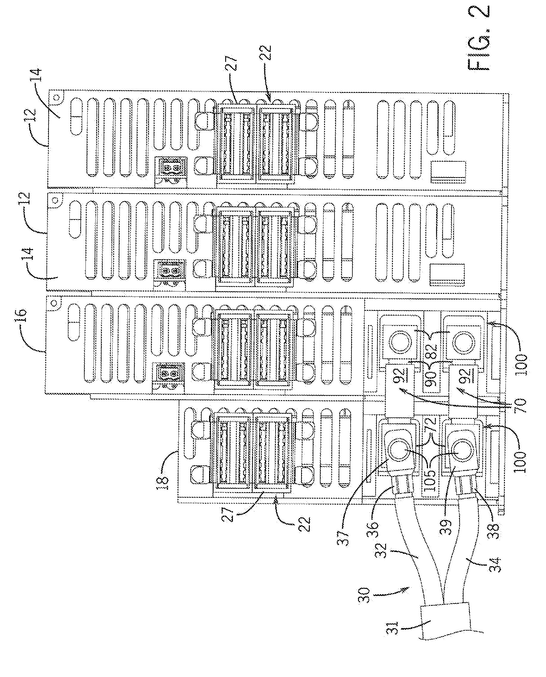
[0033]Turning initially to FIGS. 1-3, an exemplary multi-axis drive system 10 utilizing a shared DC bus 20 is illustrated. The multi-axis drive system 10 includes multiple modules, such as motor drives 12, a capacitance module 16, and an extension module 18. Each motor drive 12 may be configured to control operation of one motor, or axis, of the multi-axis drive system 10. Each motor drive 12 may include, for example, an inverter to convert a DC voltage to an AC voltage, a rectifier to convert an AC voltage to a DC voltage, a converter to convert a DC voltage at a first voltage potential to a DC voltage at a second voltage potential, or a combination thereof. According to the illustrated embodiment, each motor drive 12 receives power from the shared DC bus 20 and includes an inverter operable to convert the power received from the shared DC bus 20 to a desired AC voltage to control operation of a motor (not shown) connected to the motor drive 12.

[0034]The shared DC bus 20 is connect...


PUM


Abstract

An improved system for connecting a DC bus cable and a remote motor drive includes a capacitance module and an extension module that may each be mounted adjacent to the remote motor drive. The capacitance module includes a first DC bus connector and a second DC bus connector. The first DC bus connector includes a terminal block configured to receive a pair of conductors for the DC bus. The first DC bus connector further includes a pair of intermediate bus bars where each of the intermediate bus bars are connected at a first end to the terminal block and at a second end to a circuit board contained within the capacitance module. Traces on the circuit board are routed between the second ends of the intermediate bus bars and the second DC bus connector. The second DC bus connector is configured to be connected to DC bus bars.

Description

CROSS-REFERENCE TO RELATED APPLICATIONS[0001]This application claims priority to Indian patent application No. 1357 / DEL / 2015, filed May 14, 2015, the entire contents of which is incorporated herein by reference.BACKGROUND OF THE INVENTION[0002]The subject matter disclosed herein relates generally to a system for increasing the current capacity of a distributed motor drive system and, more specifically, to a capacitance module and an extension module mountable proximate to an inverter in the distributed motor drive system.[0003]As is known to those skilled in the art, a motor drive is used to convert energy from a first form to a second form. The input voltage may be a DC voltage having a fixed amplitude or a single phase or multi-phase AC voltage having a fixed amplitude and frequency. The output voltage may be an AC voltage having a variable frequency and / or amplitude, where the motor drive controls the frequency and amplitude supplied to the motor such that the motor rotates at a ...

Claims


Application Information

Patent Timeline
IPC IPC(8): H02J7/34H02J1/06
CPCH02J1/06H02J7/345H02J1/102H02J7/0042
Inventor OZIMEK, PATRICKBALCERAK, JOHNKOPINESS, JEREMIAHBHANSALI, VINODSHUKLA, SHAILENDRARENGABASHYAM, MAGESH SUBBARAO
Owner ROCKWELL AUTOMATION TECH
Why Eureka
Try Eureka