Ball Bag Stand and Ball Bag Engagement Structure

Active Publication Date: 2016-12-01
CHEN BENJAMIN
View PDF9 Cites 0 Cited by
  • Summary
  • Abstract
  • Description
  • Claims
  • Application Information

AI Technical Summary

Benefits of technology

[0005]It is an objective of the present invention to provide a ball bag stand and ball bag engagement structure which allows a ball bag in use to be fixed to a ball bag stand by protrudingly engaging structures and protruding flanges and allows ball bag cords to move away from the protrudingly engaging structures with one finger of a user single-handedly because of vertical smooth surfaces of the protrudingly engaging structures such that the ball bag not in use can be removed from the ball bag stand quickly.
[0006]In order to achieve the above and other objectives, the present invention provides a ball bag stand and ball bag engagement structure, comprising: a ball bag stand structure, a ball bag structure and a plurality of protrudingly engaging structures. An action force-free surface of each of the protrudingly engaging structures has a vertical smooth surface. An action force-applied surface of each of the protrudingly engaging structures has a protruding flange. The ball bag sags while the balls in the ball bag are increasing, and thus the ball bag pulls the cords to thereby not only allow the action force-applied surfaces of the fastening holes to press against the action force-applied surfaces of the

Problems solved by technology

However, the aforesaid process not only takes much time but must also be carried out inconveniently by both hands.
As a result, upon comple

Method used


Image

  • Ball Bag Stand and Ball Bag Engagement Structure
  • Ball Bag Stand and Ball Bag Engagement Structure
  • Ball Bag Stand and Ball Bag Engagement Structure

Examples


Example

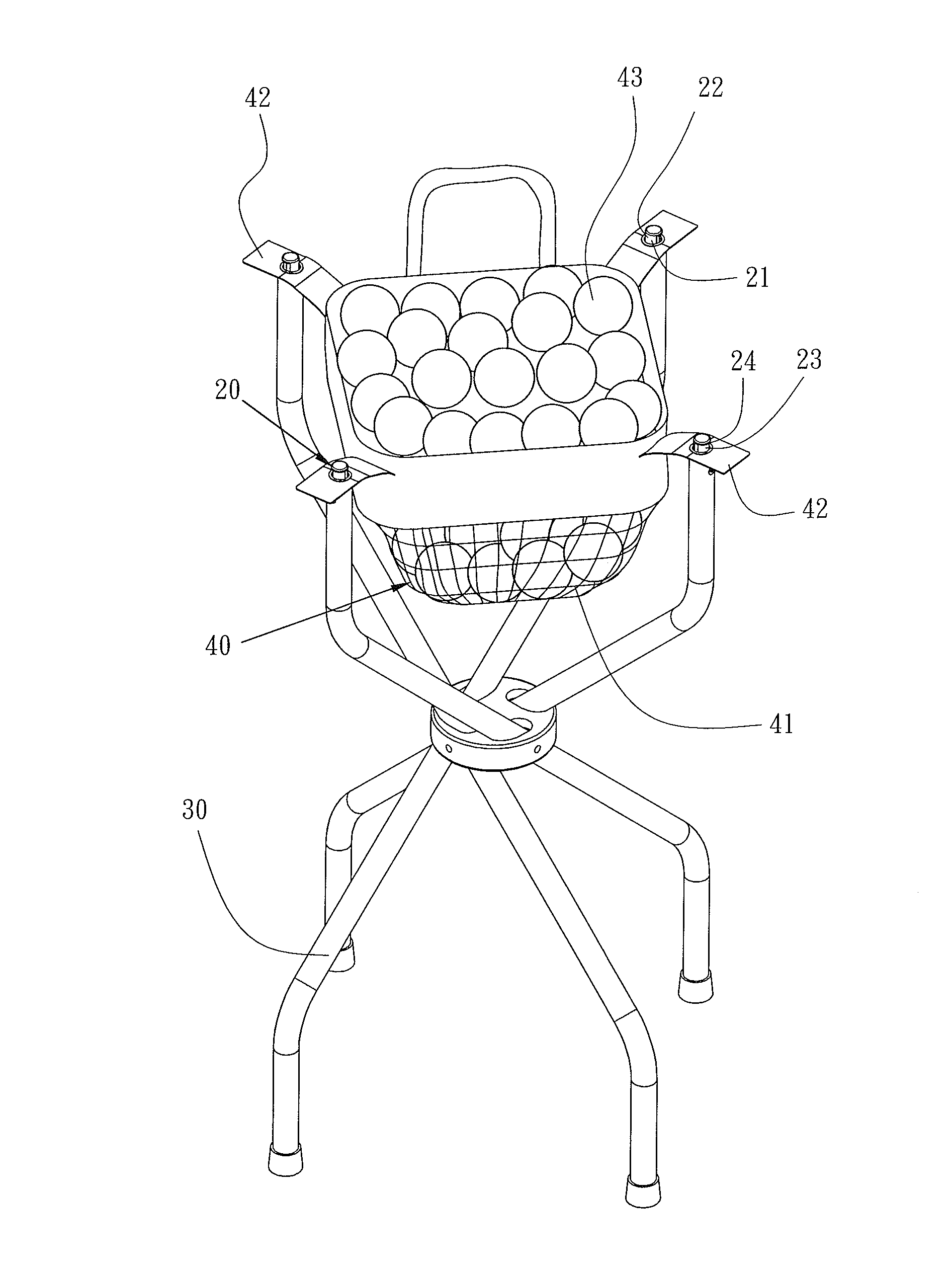
[0017]Referring to FIG. 2 through FIG. 10, the present invention provides a ball bag stand and ball bag engagement structure which comprises a plurality of protrudingly engaging structures 20 and a ball bag structure 40.

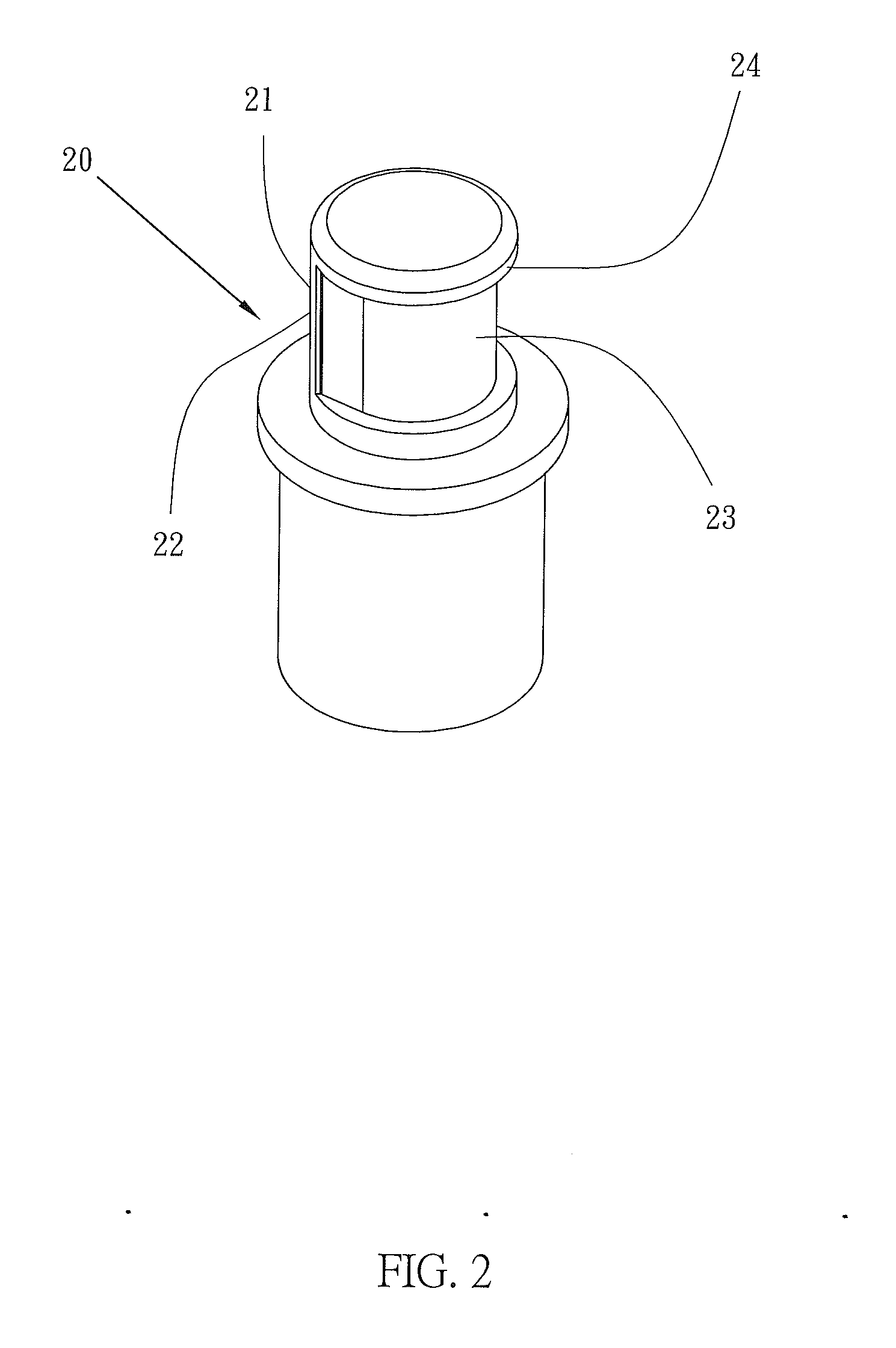
[0018]The protrudingly engaging structures 20 are each formed integrally with or coupled to a ball bag stand structure 30. The protrudingly engaging structures 20 each have an action force-free surface 21 with a vertical smooth surface 22. Furthermore, the protrudingly engaging structures 20 each have an action force-applied surface 23 with a protruding flange 24 which protrudes laterally.

[0019]The ball bag structure 40 comprises a ball bag 41 and a plurality of cords 42. The cords 42 are disposed at the periphery of the ball bag 41 and each have a fastening hole 421. The inner diameter of the fastening holes 421 is slightly larger than the outer diameter of the protrudingly engaging structures 20. The fastening holes 421 can be snap-engaged with the protrudingly eng...


PUM


Abstract

A ball bag stand and ball bag engagement structure includes a ball bag stand structure, a ball bag structure, protrudingly engaging structures, and cords. The protrudingly engaging structures each have a vertically smooth action force-free surface and an action force-applied surface with a protruding flange. A user can lift the ball bag by lifting the cords between the ball bag and the ball bag stand with one finger of the user single-handedly to thereby not only allow the action force-free surfaces of the fastening holes to press against the vertical smooth surface while sliding relative thereto, but also allow the action force-applied surfaces of the fastening holes to move away from the protruding flanges. Hence, the cords can be moved away from the protrudingly engaging structures with one finger of the user single-handedly, so that the user can remove the ball bag from the ball bag stand easily.

Description

BACKGROUND OF THE INVENTION[0001]1. Technical Field[0002]The present invention relates to the field of ball bag stands and more particularly to a ball bag stand and ball bag engagement structure which allows a ball bag in use to be fixed to a ball bag stand by protrudingly engaging structures and protruding flanges and allows ball bag cords to move away from the protrudingly engaging structures with one finger of a user single-handedly because of vertical smooth surfaces of the protrudingly engaging structures such that the ball bag not in use can be removed from the ball bag stand quickly.[0003]2. Description of Related Art[0004]Referring to FIG. 1, a conventional snap-engagement structure 10 is peripherally or circumferentially provided with a flange 11 and thus has a drawback described below. Cord fastening holes 14 disposed at a ball bag 13 engage with the flanges 11, respectively, in an increasingly tight-fitting manner while balls 12 are consecutively put in the ball bag 13. I...

Claims


Application Information

Patent Timeline
IPC IPC(8): A63B47/00B65D33/16
CPCB65D33/16A63B47/00A63B2071/025A63B2210/50B62B3/025B62B2202/40B62B3/00
Inventor CHEN, BENJAMIN
Owner CHEN BENJAMIN
Why Eureka
Try Eureka