Steering apparatus

a steering wheel and steering wheel technology, applied in the direction of electric steering, power steering, vehicle components, etc., can solve the problem of unintended steering wheel rotation by the driver

Inactive Publication Date: 2016-12-01
JTEKT CORP
View PDF7 Cites 4 Cited by
  • Summary
  • Abstract
  • Description
  • Claims
  • Application Information

AI Technical Summary

Benefits of technology

[0009]When the clutch is engaged, the reaction force control through the reaction force motor and the steering operation control through the steering operation motor may each be continuously executed. Thus, when the clutch is engaged, an operation of steering the steered wheel may be transmitted to the steering wheel through the power transmission path even for a short period of time. This may cause rotation of the steering wheel unintended by a driver. In this regard, the above-described configuration suppresses rotation of the steering wheel through the rotation suppression control that uses at least the reaction force motor when the clutch is engaged. Thus, rotation of the steering wheel unintended by the driver is suppressed.

Problems solved by technology

This may cause rotation of the steering wheel unintended by a driver.

Method used


Image

  • Steering apparatus
  • Steering apparatus
  • Steering apparatus

Examples


first embodiment

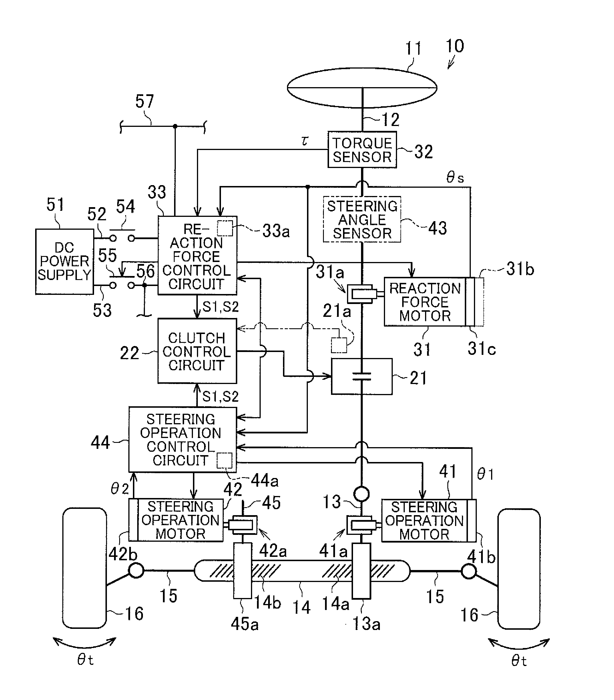
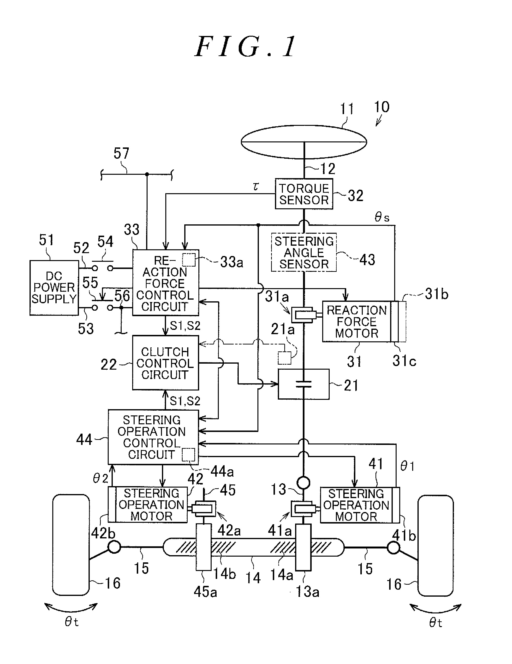
[0014]A steer-by-wire steering apparatus that is the present invention will be described below. As depicted in FIG. 1, a steering apparatus 10 for a vehicle has a steering shaft 12 coupled to a steering wheel 11. A first pinion shaft 13 is provided at an end of the steering shaft 12 opposite to the steering wheel 11. Pinion teeth 13a of the first pinion shaft 13 are meshed with first rack teeth 14a of a steered shaft 14 extending in a direction crossing the pinion teeth 13a. Right and left steered wheels 16, 16 are coupled to respective opposite ends of the steered shaft 14 via respective tie rods 15, 15. The steering shaft 12, the first pinion shaft 13, and the steered shaft 14 function as a power transmission path between the steering wheel 11 and the steered wheels 16, 16. That is, in conjunction with an operation of rotating the steering wheel 11, the steered shaft 14 moves linearly to vary a steered angle θt of the steered wheels 16 and 16.

[0015]The steering apparatus 10 also h...

second embodiment

[0086]Therefore, the second embodiment can produce the following effects.

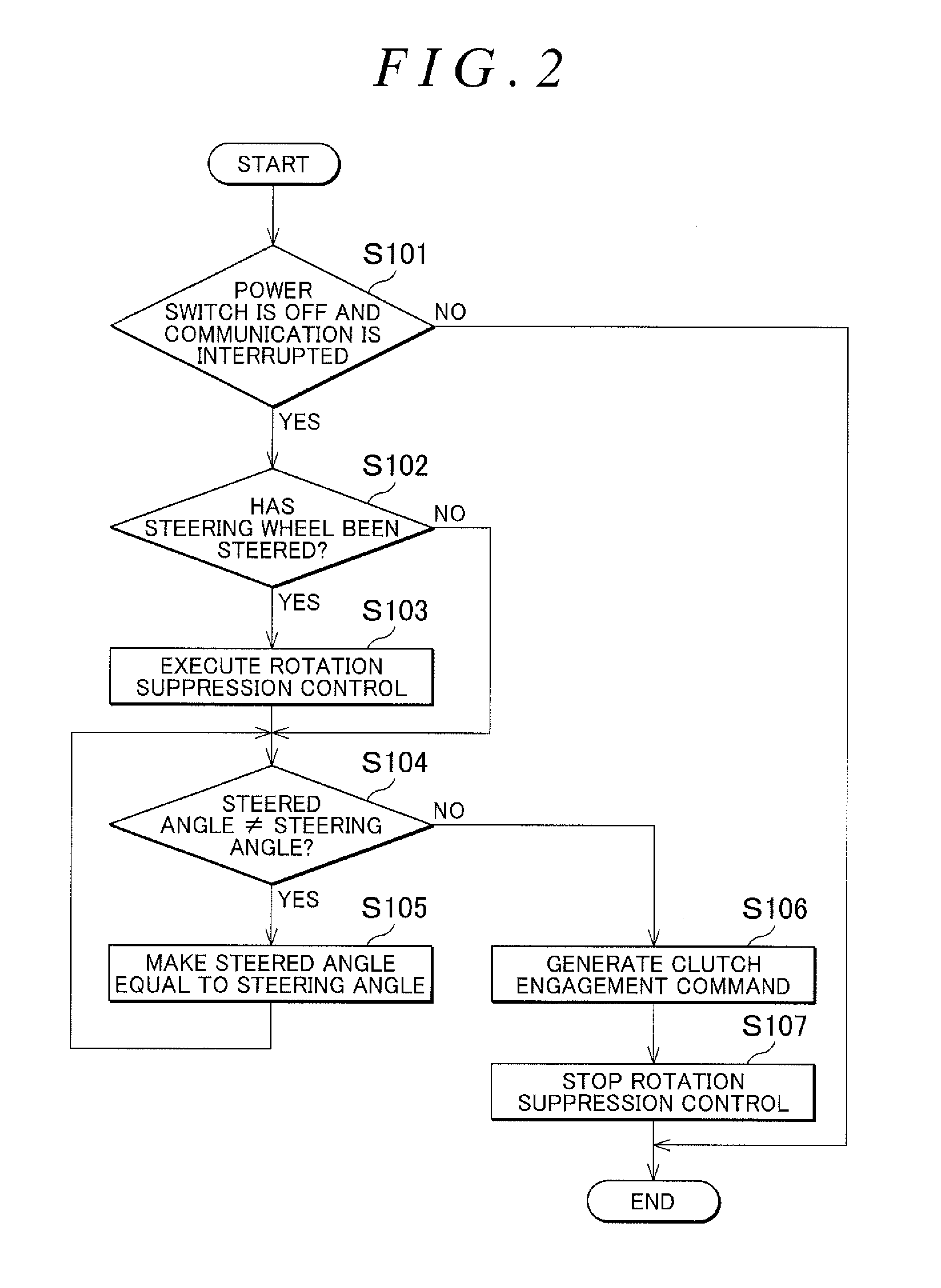
[0087](1) When an abnormality is detected in at least one of the reaction force unit and the steering operation unit, the clutch 21 is engaged. At this time, the phase fixing control is executed on each of the reaction force motor 31 and the first and second steering operation motors 41, 42 after the clutch engagement command S1 is generated until engagement of the clutch 21 is completed. This makes suppression of an unintended rotating operation of the steering wheel 11 and an unintended operation of steering the steered wheels 16, 16 that result from execution of the reaction force control and the steering operation control based on an abnormal sensor signal.

[0088](2) After engagement of the clutch 21 is completed, execution of the phase fixing control on each of the reaction force motor 31 and the first and second steering operation motors 41, 42 is stopped to enable the steered wheels 16, 16 to be steered u...


PUM


Abstract

A steering apparatus is provided which can suppress unintended movement of a steering wheel when a clutch is engaged. When a power switch is turned off and a steering wheel is steered, a reaction force control circuit makes a reaction force motor to generate a steering reaction force stronger than a normal steering reaction force to give a driver an appropriate feeling of response according to a steering torque. The strong steering reaction force is applied to a steering shaft to suppress steering of the steering wheel. A steering operation control circuit executes steering operation control, that is, control that makes an actual steered angle equal to a target steered angle based on a steering angle, and then a clutch is engaged. The clutch is engaged after confirmation of an immovable state of steered wheels, and thus rotation of the steering wheel unintended by the driver is suppressed.

Description

INCORPORATION BY REFERENCE[0001]The disclosure of Japanese Patent Application No. 2015-109710 filed on May 29, 2015 and No. 2015-181010 filed on Sep. 14, 2015 including the specification, drawings and abstract, is incorporated herein by reference in its entirety.BACKGROUND OF THE INVENTION1. Field of the Invention[0002]The invention relates to a steering apparatus for a vehicle.2. Description of the Related Art[0003]What is called steer-by-wire steering apparatuses are conventionally known in which a steering wheel is mechanically separated from steered wheels. For example, a steering apparatus in Japanese Patent Application Publication No. 2014-223862 (JP 2014-223862 A) has a clutch that connects and disconnects a power transmission path between the steering wheel and the steered wheels, a reaction force motor that is a source of a steering reaction force applied to the steering shaft, and a steering operation motor that is a source of a steering operation force making the steered ...

Claims


Application Information

Patent Timeline
Patent Type & Authority Applications(United States)
IPC IPC(8): B62D5/04
CPCB62D5/0478B62D5/0433B62D5/043B62D5/046B62D5/0475B62D6/008B62D5/001B62D5/003
Inventor MATSUDA, SATOSHIYAMAKAWA, TOMONARI
Owner JTEKT CORP
Why Eureka
Try Eureka