Device for positioning an object at a user-adjusted position

a technology for positioning objects and objects, applied in the field of devices for positioning objects at user-adjusted positions, can solve the problem of relatively low cycle life of devices, and achieve the effect of facilitating the intended movement of objects

Active Publication Date: 2017-04-18
SOUTHCO
View PDF19 Cites 2 Cited by
  • Summary
  • Abstract
  • Description
  • Claims
  • Application Information

AI Technical Summary

Benefits of technology

[0004]According to one aspect, this inventions provides a device for positioning an object with respect to another object. The device includes a linkage having an extended condition and a collapsed condition, the linkage including at least one pair of links coupled to one another about a rotation axis. The device also includes a friction element positioned at the rotation axis of the at least one pair of links of the linkage. A spring of the device is positioned to apply bias to the links of the at least one pair of links of the linkage. The device is configured to resist unintended movement of the object from the user-adjusted position along the path and to facilitate intended movement of the object proximally toward or distally away from the other object.
[0006]According to another aspect, this invention also provides a user-adjustable positioning system. The system includes a first object movable by a user of the system and a second object with respect to which the first object is movable along a path proximally toward or distally away from the second object. The system also includes a linkage having a distal end portion coupled to the first object and a proximal end portion coupled to the second object, the linkage also having an extended condition and a collapsed condition. The linkage includes at least one pair of links coupled to one another about a rotation axis, and a friction element is positioned at the rotation axis of the at least one pair of links of the linkage. A spring is positioned to apply bias to the links of the at least one pair of links of the linkage. The linkage is configured to resist unintended movement of the first object from the user-adjusted position along the path and to facilitate intended movement of the first object proximally toward or distally away from the second object.

Problems solved by technology

Some such devices have a relatively low cycle life and may fall prematurely.

Method used


Image

  • Device for positioning an object at a user-adjusted position
  • Device for positioning an object at a user-adjusted position
  • Device for positioning an object at a user-adjusted position

Examples


Embodiment Construction

[0025]Although the invention is illustrated and described herein with reference to specific embodiments, the invention is not intended to be limited to the details shown. Rather, various modifications may be made in the details within the scope and range of equivalents of the claims and without departing from the invention.

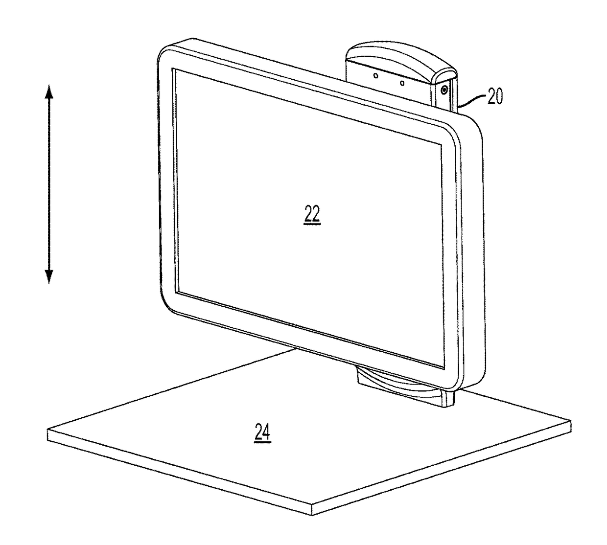
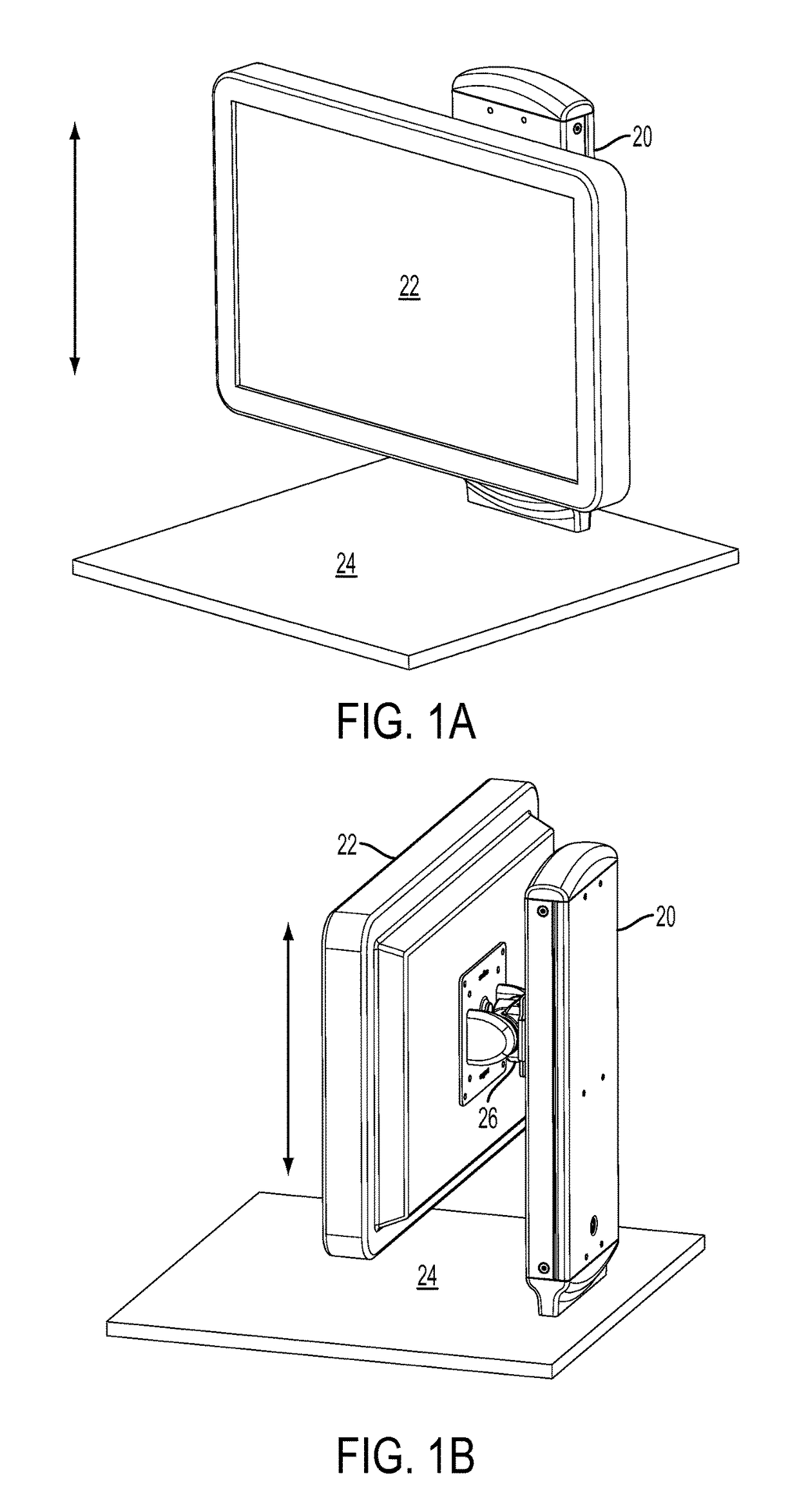
[0026]According to one aspect, this invention provides a vertical lift mechanism that can be used to position a moveable object at a user adjusted position with respect to a stationary base, and can allow the moveable object to remain at that position until the user re-adjusts the moveable object. The mechanism also provides a counterbalancing effect so that the user force input to position the moveable object is less than the weight of the moveable object itself. This user force input is nearly constant over the range of motion of the mechanism.

[0027]One specific application for this mechanism is to vertically position a monitor with respect to a desktop or cart ...


PUM


Abstract

A device is provided for positioning an object with respect to another object. The device includes a linkage having an extended condition and a collapsed condition, the linkage including at least one pair of links coupled to one another about a pivot rotation axis. The device also includes a friction element positioned at the pivot rotation axis of the at least one pair of links of the linkage. A spring of the device is positioned to apply bias to the links of the at least one pair of links of the linkage. The device is configured to resist unintended movement of the object from the user-adjusted position along the path and to facilitate intended movement of the object proximally toward or distally away from the other object.

Description

CROSS REFERENCE TO RELATED APPLICATION[0001]This application claims the benefit of U.S. Provisional Application No. 62 / 003,749, filed May 28, 2014, the contents of all of which are incorporated herein by reference in their entirety.BACKGROUND OF THE INVENTION[0002]Devices have been proposed in the past for positioning an object at a user-adjusted position. Some such devices have a relatively low cycle life and may fall prematurely. Other devices may require adjustment by the user in order to be configured for use with objects of different weights. Still other devices require a lever or brake mechanism in order to secure an object in a user-adjusted position.[0003]Although one or more of these characteristics may be acceptable or even desirable in some circumstances, there remains a need for improved devices for positioning an object at a user-adjusted position that can optionally eliminate one or more of these characteristics. There also remains a need for a device improved in terms...

Claims


Application Information

Patent Timeline
Patent Type & Authority Patents(United States)
IPC IPC(8): F16M11/00F16M11/38F16M13/02F16C11/04F16M11/04
CPCF16C11/04F16M11/046F16M11/38F16M13/02F16M2200/047F16M2200/08Y10T403/32016A47B9/02A47B21/02A47B23/043F16M13/022A47B2023/049
Inventor SCHLACK, RICHARD E.
Owner SOUTHCO
Why Eureka
Try Eureka