
Device, system and method for visualization of patient-related data

Active Publication Date: 2016-12-01
KONINKLJIJKE PHILIPS NV
View PDF4 Cites 11 Cited by
  • Summary
  • Abstract
  • Description
  • Claims
  • Application Information

AI Technical Summary

Benefits of technology

The patent aims to provide a system and method for visualizing patient-related data to help caregivers better understand and use the information in diagnosis and decision support. The invention also includes a patient monitor.

Problems solved by technology

The large amount of available patient-related data for a single patient provides many benefits, but poses also challenge, in particular for clinicians and physicians (or, generally, any caregivers or users) trying to make sense of the patient's condition and understand the patient's medical history.

Method used


Image

  • Device, system and method for visualization of patient-related data
  • Device, system and method for visualization of patient-related data
  • Device, system and method for visualization of patient-related data

Examples


first embodiment

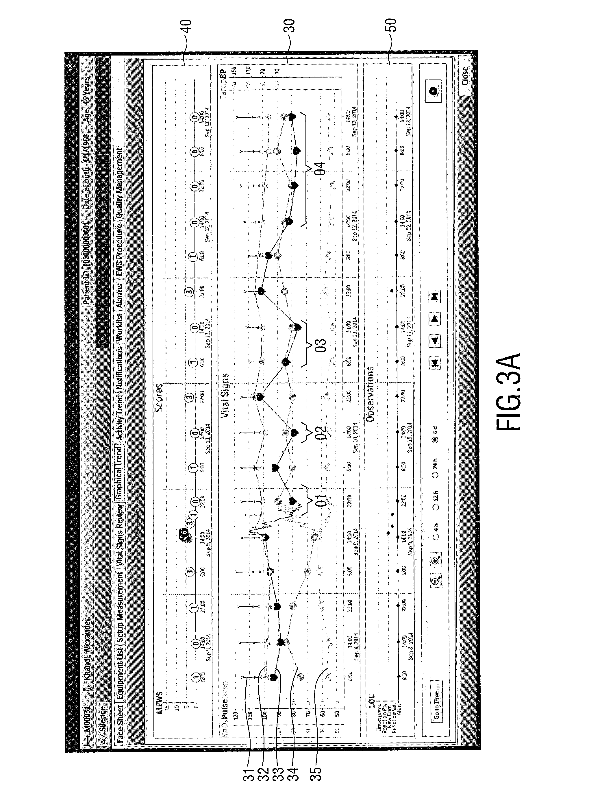
[0055]FIG. 3A shows a timing diagram 30 in which several plots (also called trends) are visualized over time, including (from top to bottom) a plot 31 for blood pressure (BP) a plot 32 for temperature (Temp), a plot 33 for heart rate (Pulse), a plot 34 for blood oxygen saturation (SpO2) and a plot 35 for respiration rate (Resp). In this embodiment the plots 32 to 35 are visualized as lines connecting the available parameter values of the respective patient-related parameter. Further, the parameter values are separately indicated by different icons (e.g. dots for SpO2, hearts for HR). The plot 31 for blood pressure is indicated by range indications indicating the systolic, mean and diastolic pressure at the respective moment in time.

[0056]As can be seen in FIG. 3A the plots are generally arranged such that they do not overlap (i.e. cross each other) which shall be understood such that the respective parameters are in an uncritical range, i.e. the health condition of the patient is un...

second embodiment

[0060]FIG. 3B shows different diagrams. Compared to the diagrams shown in FIG. 3A the score diagram 41 is slightly different than the score diagram 40. The score diagram 41 indicates, in addition to the MEWS, sepsis, in particular if SIRS (systemic inflammatory response syndrome) is given (SIRS) at a certain moment (which is the case in this example on days 2, 3 and 4).

third embodiment

[0061]FIG. 3C shows different diagrams. Compared to the diagrams shown in FIG. 3B the score diagram 42 is slightly different by not only indicating if SIRS is given but also if sepsis is suspected (Susp) (which is the case in this example on day 2). Further, the observations diagram 52 additionally indicates if a new infection (New Inf.) is detected (which is the case in this example on day 2), which easily allows recognizing if a caregiver should take a close look.


PUM


Abstract

The present invention relates to device, system and method for visualization of patient-related data. To enable a user, such as a caregiver, to quickly and easily recognize if the patient's health conditions has become critical, the propose device comprises a processor for processing the obtained patient-related data for visualization. The processor is configured to generate time-dependent plots of at least two different patient-related parameters over time derived from the obtained patient-related data. Said plots are generated for common visualization in a common timing diagram on a display, wherein the scale, baseline, position and range of the plots are selected to visualize the plots in the common timing diagram without overlap at times, at which the parameter values of the respective parameters visualized by the plots are considered uncritical for the patient's health condition, and to visualize a plot with overlap with another plot at times, at which the parameter values of the parameter of said plot are considered critical for the patient's health condition.

Description

CROSS REFERENCE TO RELATED APPLICATION[0001]This application claims the benefit of European Patent Application Number 15169147.4 filed May 26, 2015. This application is hereby incorporated by reference herein.FIELD OF THE INVENTION[0002]The present invention relates to a device, system and method for visualization of patient-related data. Further, the present invention relates to a patient monitor.BACKGROUND OF THE INVENTION[0003]Patient monitors are widely used in healthcare, e.g. in ICUs or generally in hospitals, to monitor and visualize patient-related data, in particular clinical data such as vital signs, scores and other information related to the patient's condition. For instance, the well-known Philips IntelliVue patient monitors provide a clear view of patient information and use highly configurable screens and clinical decision support tools that reflect clinical thought processes. IntelliVue monitors collect, combine, and cross-reference physiologic data to provide a cohe...

Claims


Application Information

Patent Timeline
IPC IPC(8): G06F19/00
CPCG06F19/345G06F19/322A61B5/742A61B5/746G16H10/60G16H40/63G16H50/20
Inventor STOCKER, PHILIPP
Owner KONINKLJIJKE PHILIPS NV
Learn More