Connector

a technology of connectors and housings, applied in the direction of connection, electrical apparatus, coupling device connections, etc., can solve the problems of affecting the service life of the counterpart connector, the shape of the counterpart connectors becomes complicated, and the retainer protruding from the outer periphery of the housing may hit the counterpart connector, so as to simplify the housing of the counterpart connector. , the effect of downsizing the connector

Inactive Publication Date: 2016-12-01
YAZAKI CORP
View PDF13 Cites 7 Cited by
  • Summary
  • Abstract
  • Description
  • Claims
  • Application Information

AI Technical Summary

Benefits of technology

[0005]Illustrative aspects of the present invention provide a connector capable of downsizing the connector, simplifying a housing of a counterpart connector, and facilitating a work for coupling the connectors to each other.
[0007]According to another illustrative aspect of the present invention, the outer surface of the retainer may not be flush with the outer peripheral surface of the housing body when the retainer is in the closed position, but the retainer has a base end at which the retainer is connected to the housing body via the hinge and a free end on a side opposite to the base end, the free end being opposed to a locking surface forming the opening portion in a state in which the retainer is in the closed position, one of the free end of the retainer and the locking surface of the opening portion has at least on locking portion at which the other of the free end of the retainer and the locking surface of the opening portion is locked, and one of the free end of the retainer and the locking surface of the opening portion has a recessed portion that forms a hole portion between the recessed portion and the other of the free end of the retainer and the locking surface of the opening portion. According to this configuration, the retainer can be reliably locked thereby locking the terminal, and the retainer can be opened easily when necessary.

Problems solved by technology

In this connector, a portion of the retainer locking the terminal protrudes from an outer peripheral surface of the housing, resulting in an increase in size.
Therefore, the shape of the housing of the counterpart connector becomes complicated.
Further, when coupling the connector to the counterpart connector, the retainer protruding from the outer periphery of the housing may hit the counterpart connector.

Method used


Image

  • Connector
  • Connector
  • Connector

Examples


Embodiment Construction

[0022]Hereinafter, exemplary embodiments of the present invention will be described in detail with reference to the drawings. However, the following exemplary embodiments do not limit the scope of the claimed invention.

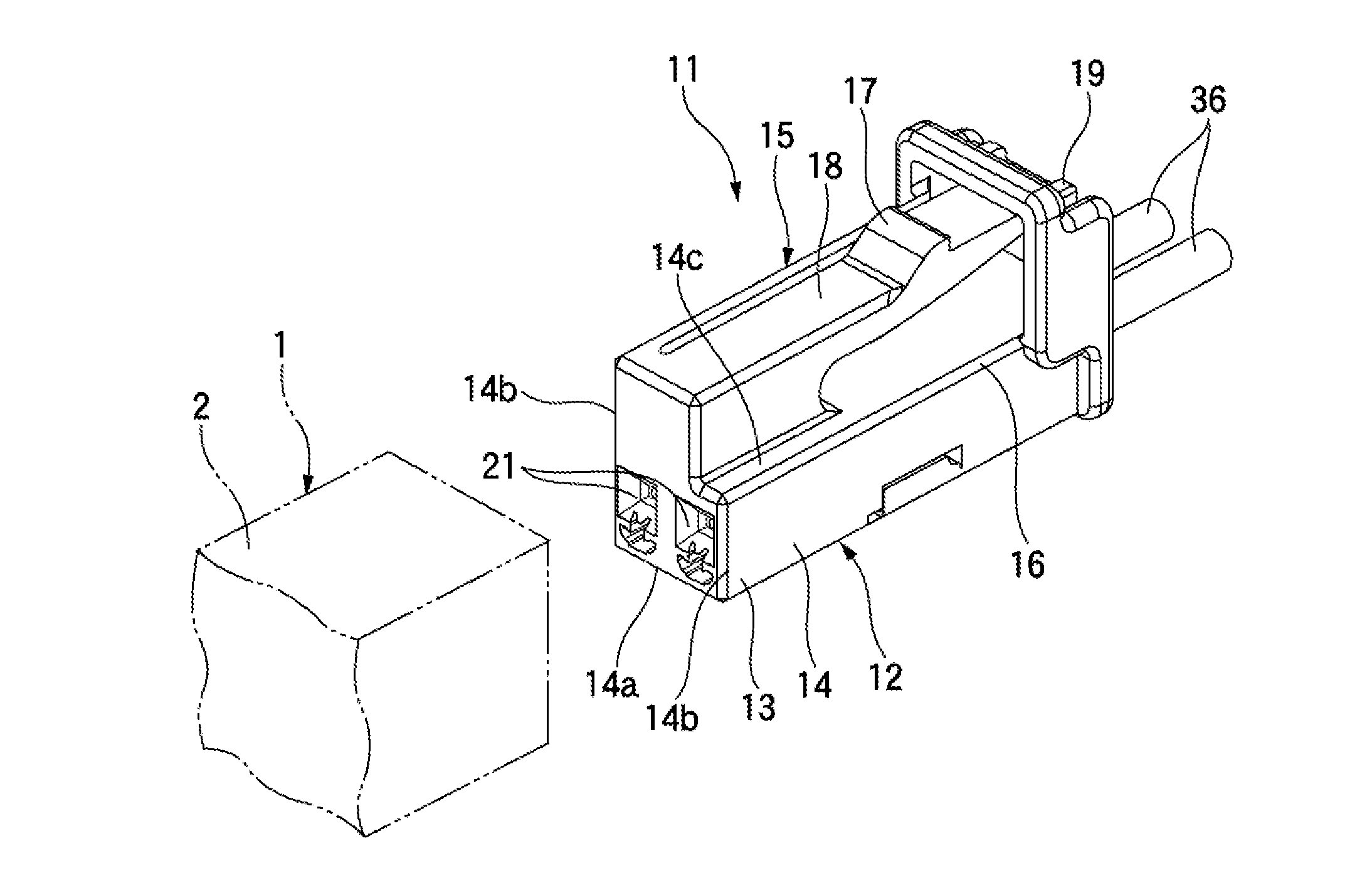
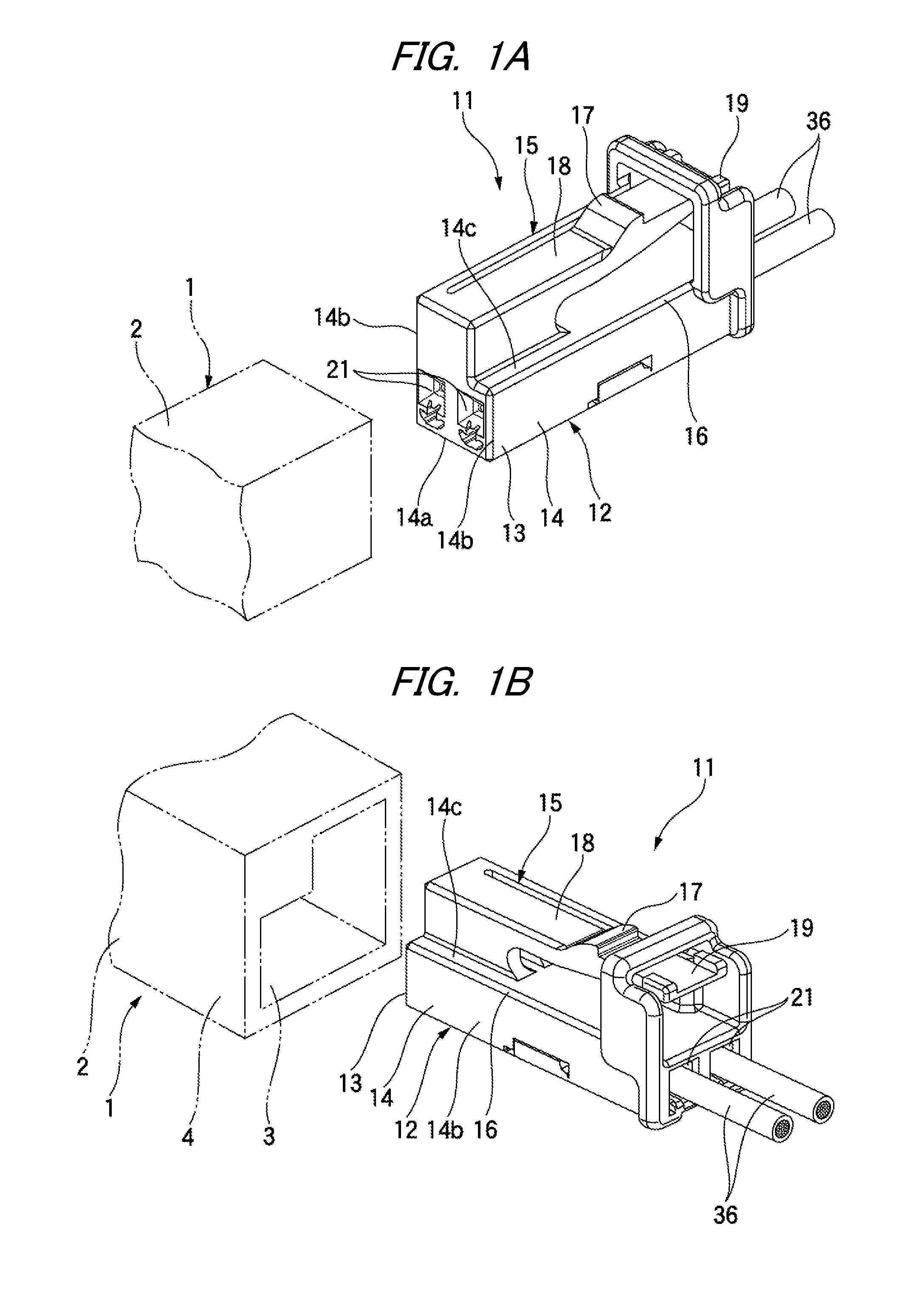
[0023]As shown in FIGS. 1A and 1B, a connector 11 according to the exemplary embodiment of the invention has a female housing 12 made of a resin molded product, and a counterpart connector 1 has a male housing (housing) 2 made of a resin molded product. The female housing 12 has a fitting portion 13 on its distal end side, which is the front side in the direction in which the connector 11 is coupled to the counterpart connector 1. The male housing 2 has a fitting recessed portion 3 on its distal end side, which is the front side in the direction in which the connector 1 is coupled to the connector 11. The male housing 2 has a hood portion 4. The inside of the hood portion 4 serves as the fitting recessed portion 3. When the fitting portion 13 of the female housing 12 ...


PUM


Abstract

A connector includes a terminal, a housing body haying a terminal housing chamber inside which the terminal is housed, an opening portion formed at an outer peripheral surface of the housing body, a retainer having a locking protrusion that protrudes into the terminal housing chamber to lock the terminal housed in the terminal housing chamber when the retainer is fitted to the opening portion, and a hinge that connects the retainer to the housing body so as to allow the retainer to turn between an open position at which the opening portion is opened and a closed position at which the retainer is fitted to the opening portion to close the opening portion. When the retainer is in the closed position, an outer surface of the retainer is flush with the outer peripheral surface of the housing body.

Description

CROSS-REFERENCE TO RELATED APPLICATIONS[0001]The present application claims priority from Japanese Patent Application Nos. 2015-108754 and 2015-108755 both filed on May 28, 2015, the entire contents of which are incorporated herein by reference.FIELD OF INVENTION[0002]The present invention relates to a connector provided with a terminal.RELATED ART[0003]A related art connector is coupled to a counterpart connector such that a terminal provided in a housing is electrically connected to a terminal of the counterpart connector. The connector has a retainer attached to the housing. The retainer is pushed into an opening portion of the housing so that the terminal can be locked by the retainer (see, e.g., JP2001-332333A and JPH08-17504A).[0004]In this connector, a portion of the retainer locking the terminal protrudes from an outer peripheral surface of the housing, resulting in an increase in size. In addition, a housing of the counterpart connector has to be formed so as to conform to ...

Claims


Application Information

Patent Timeline
Patent Type & Authority Applications(United States)
IPC IPC(8): H01R13/422H01R13/631
CPCH01R13/631H01R13/422H01R13/4223H01R13/4361H01R13/6272
Inventor NAGAI, KENTAROWADA, YOSHIMINAGASAKA, NAOKAZUJIN, DACHENG
Owner YAZAKI CORP
Why Eureka
Try Eureka