
Device for controlling transmission of radiation

a technology for controlling radiation and radiation transmission, applied in the direction of instruments, optics, non-linear optics, etc., to achieve the effect of simplifying and/or flexible production processes, and reducing the number of different elements

Active Publication Date: 2019-07-11
MERCK PATENT GMBH
View PDF7 Cites 1 Cited by
  • Summary
  • Abstract
  • Description
  • Claims
  • Application Information

AI Technical Summary

Benefits of technology

The patent text describes a device that controls the transmission of radiation. The device is made up of two paired substrates, which are designed to fit together and not extend beyond the edges of the device. The substrates are easy to produce from blank substrates that are commercially available. The technical effect of this design is that the device is compatible with conventional glazing systems, such as windows and insulating glass windows, which makes it easier to process and reduces costs. The device can also have electrical wiring attached to it after production, allowing for more flexibility in its installation.

Problems solved by technology

Furthermore, they are available in small sizes and / or lightweight.

Method used


Image

  • Device for controlling transmission of radiation
  • Device for controlling transmission of radiation
  • Device for controlling transmission of radiation

Examples


Embodiment Construction

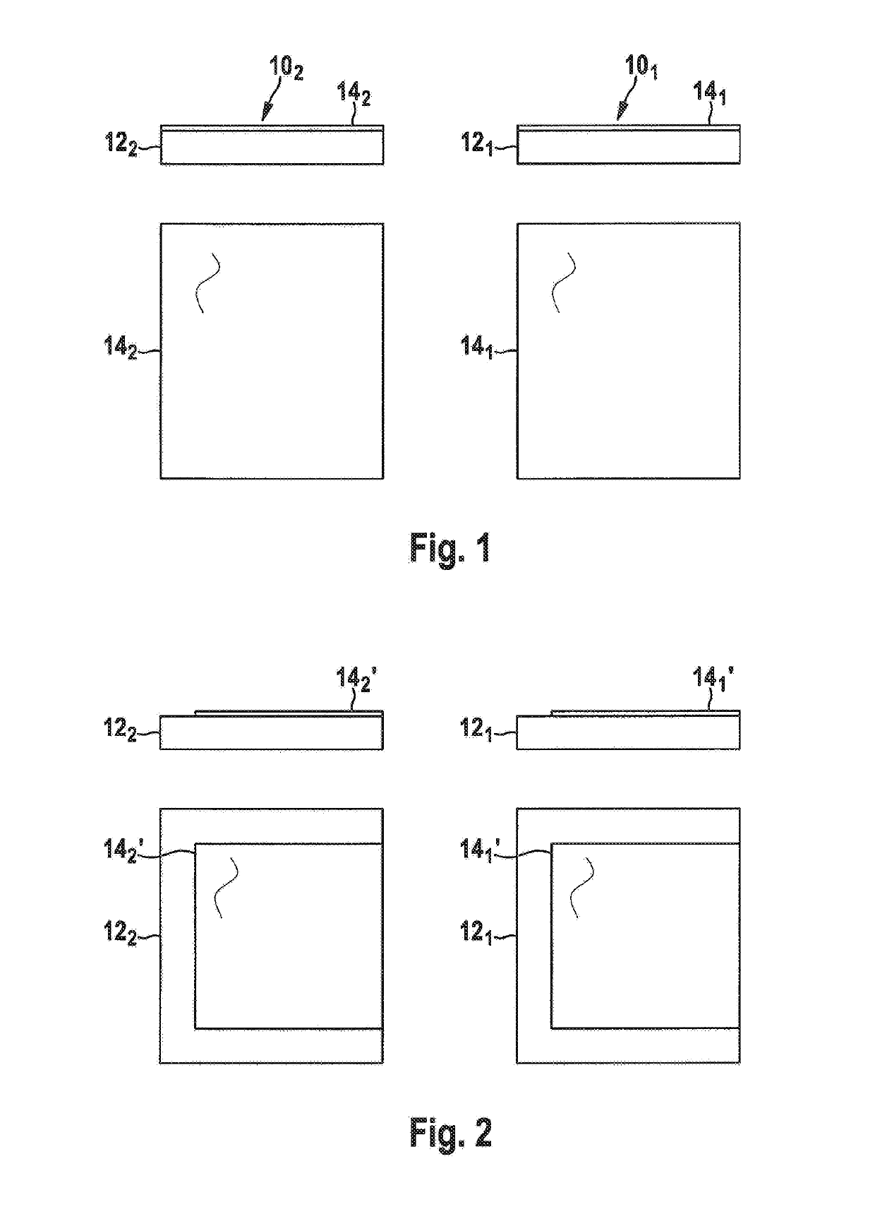
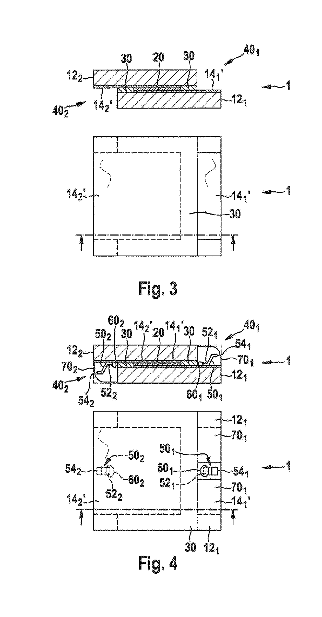
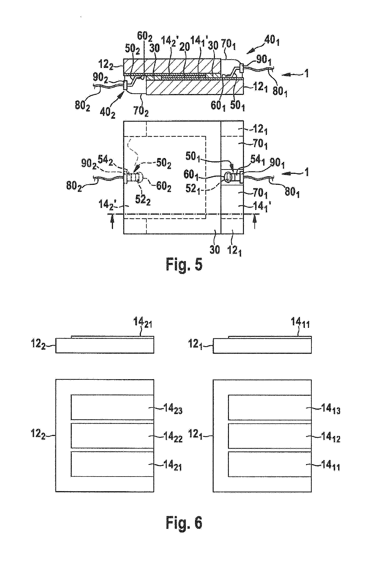
[0077]In the detailed description of the embodiments, reference is made to the accompanying drawing which forms a part hereof and shows, by way of illustration, specific embodiments in which the invention may be practiced. In order to show the structures of the embodiments most clearly, the drawing included herein is a diagrammatic representation of inventive articles. Thus, actual appearance of the fabricated structures may appear different while still incorporating essential structures of embodiments. Moreover, the drawing shows only the structures necessary to understand the embodiments. Additional structures known in the art have not been included to maintain clarity of the drawings. It is also to be understood, that features and / or elements depicted herein are illustrated with particular dimensions relative to one another for purposes of simplicity and ease of understanding, and that actual dimensions may differ substantially from that illustrated herein. In the drawing, like n...


PUM

PropertyMeasurementUnit
Shapeaaaaaaaaaa
Electric potential / voltageaaaaaaaaaa

Abstract

Device for controlling transmission of radiation, comprises a first substrate comprising a first conductive layer; a second substrate comprising a second conductive layer; an active layer positioned between the first and second conductive layers for controlling the transmission of radiation by altering its light transmissivity dependent on a voltage applied to the first and second conductive layers; a first contact providing a first electrical connection to the first conductive layer; a first portion of an adhesive or solder for attaching a first proximal end of the first contact to the first conductive layer; a second contact providing a second electrical connection to the second conductive layer; and a second portion of adhesive or solder for attaching a second proximal end of the second contact to the first or second conductive layer.

Description

FIELD OF THE INVENTION[0001]Embodiments of the invention described herein relate generally to controlling transmission of radiation, and more particularly to a device and method for controlling transmission of radiation, for example electromagnetic radiation (EMR) such as light, in particular visible light, or ultraviolet (UV) i. e. heat, in a window or display.BACKGROUND OF THE INVENTION[0002]In the sense of the present application, Light means electromagnetic radiation in the range of 320 nm to 3 μm, i. e. in the near ultraviolet (NUV), including the ultraviolet-A (UV-A), visible (VIS) and near infrared (NIR) spectrum, and heat means electromagnetic radiation in the range of 3 μm to 1 mm, i. e. in the mid infrared (MIR-) and far infrared (FIR) spectrum.[0003]Devices for controlling, e. g. switching, transmission of radiation, e. g. light and heat, mean devices having at least two states, where in one state (dark state, scattering state, absorptive state, off state) of these states...

Claims


Application Information

Patent Timeline
IPC IPC(8): G02F1/1345G02F1/155G02F1/1676G02F1/167
CPCG02F1/13452G02F1/155G02F1/1676G02F1/167G02F1/1334G02F2201/56
Inventor DE JONG, TIESVAN OOSTEN, CASPER
Owner MERCK PATENT GMBH
Learn More