
Additive manufacturing apparatus and method for operating the apparatus

a technology of additive manufacturing and process chamber, which is applied in the direction of additive manufacturing processes, manufacturing tools, and applying layer means, etc., can solve the problems of minor perturbations of laminar flow, less expensive and reliable garage doors, and inability to completely avoid minor perturbations. , to achieve the effect of reducing the down time of the laser and reducing the effect of unintended dust migration

Pending Publication Date: 2021-12-30
SLM SOLUTIONS GRP
View PDF7 Cites 0 Cited by
  • Summary
  • Abstract
  • Description
  • Claims
  • Application Information

AI Technical Summary

Benefits of technology

This patent is about a way to make 3D objects faster using a process called additive manufacturing. It solves a problem by reducing the time it takes to make each layer of the object by controlling the flow of a protective gas. The patent also describes a design for the process chamber housing, which has two doors - one for safety and one to guide the gas flow. The design can be easily retrofitted to existing housings. Overall, this invention makes 3D printing faster and more efficient.

Problems solved by technology

In case the first side wall's first movable portion is closed and the recoater is parked in its first position, the recoater does not affect the laminar inert gas flow and in particular does not provide for any turbulences or vortices which may cause unintended transportation of powder.
This provides a less expensive and reliable garage door, which may be provided by the first movable portion of the first side wall.
Theoretically, the optimum distance would be the thickness of the laminar boundary layer, however in practice minor perturbations of the laminar flow cannot be entirely avoided, for example because small gaps between static and movable portions of the first and second side walls cannot be avoided.

Method used


Image

  • Additive manufacturing apparatus and method for operating the apparatus
  • Additive manufacturing apparatus and method for operating the apparatus
  • Additive manufacturing apparatus and method for operating the apparatus

Examples


Embodiment Construction

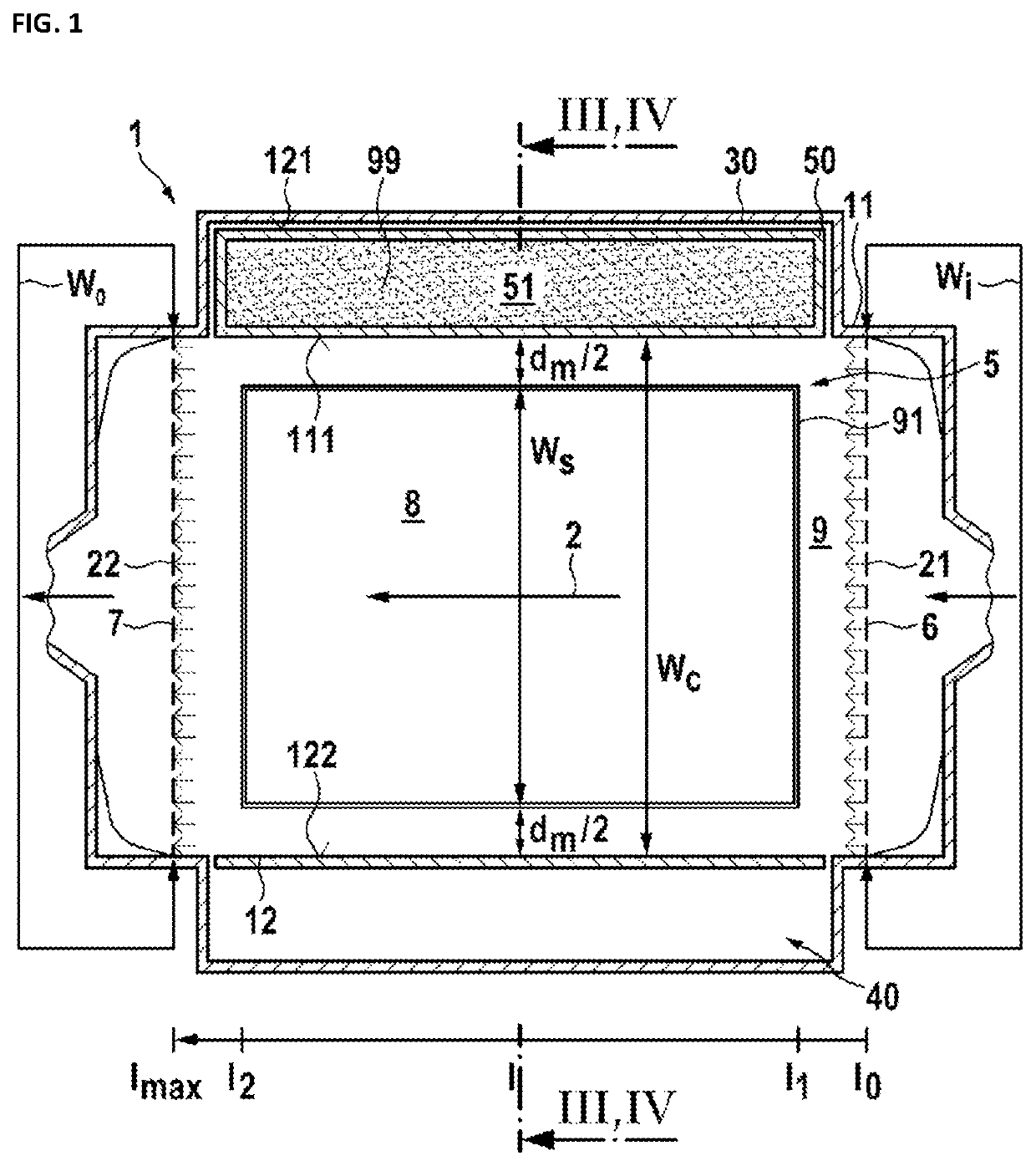
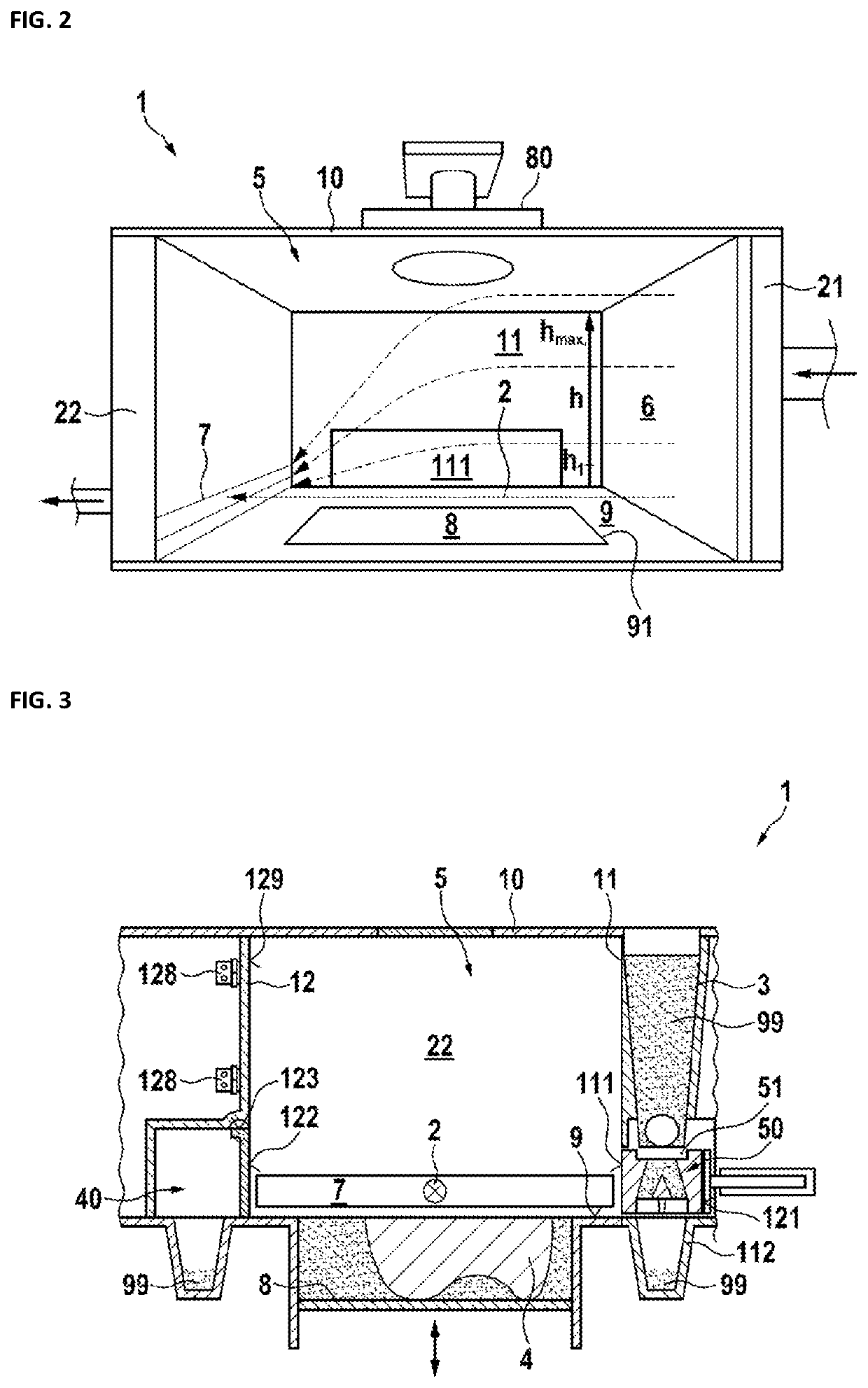
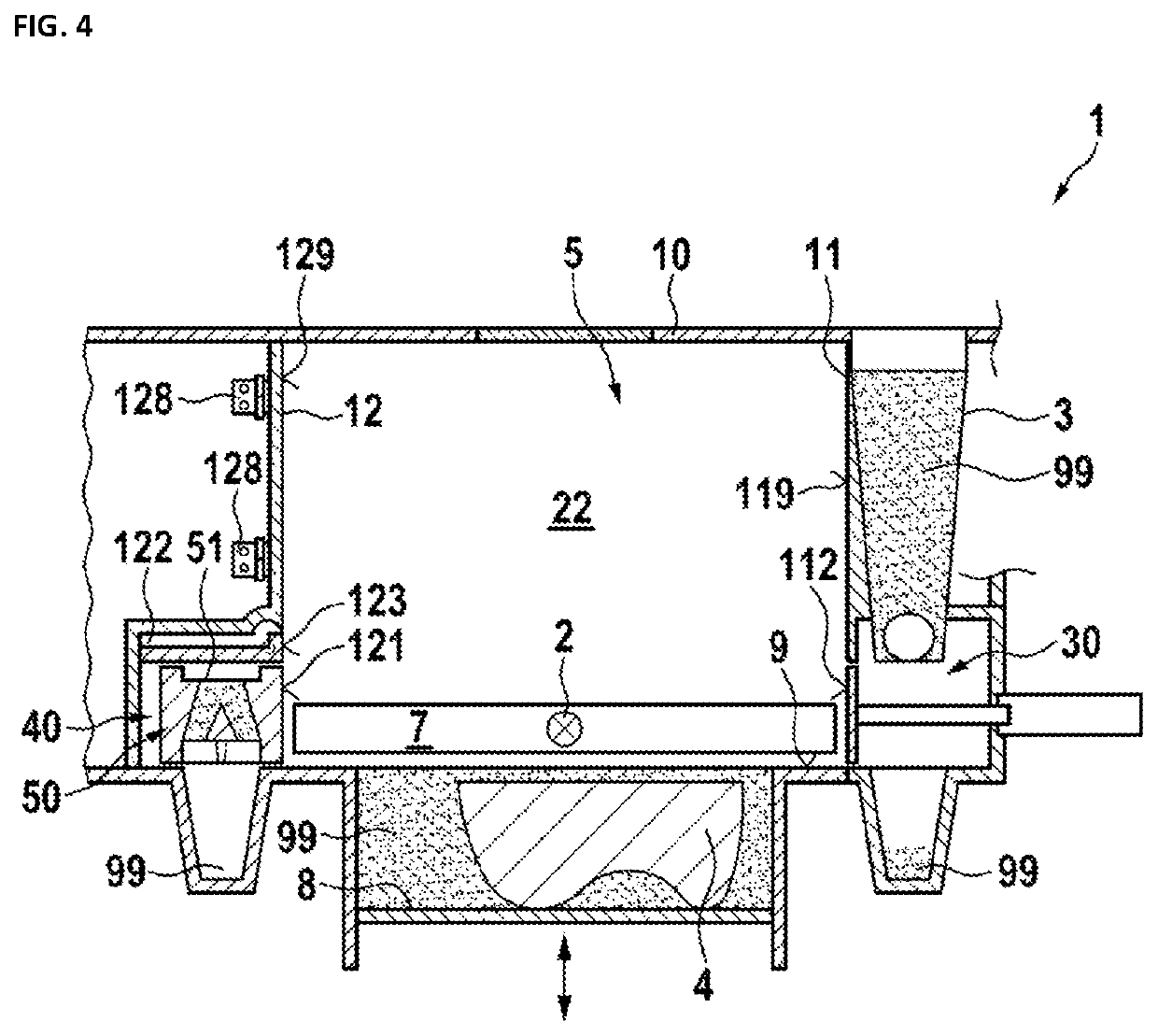
[0084]FIG. 1 shows a simplified sketch of a process chamber housing 1 as viewed at a position approximately corresponding to the height h1as shown in FIG. 2. FIG. 2 is a perspective side view of a process chamber housing 1 of FIG. 1, but in which perspective side view a second side wall 12 (expressly shown in FIG. 1) has been removed. Together, FIGS. 1 and 2 illustrate an embodiment of the process chamber housing. The process chamber housing 1 has a first sidewall 11 and a second side wall 12 being opposed to each other and having a length lmax. Further, the process chamber 5 (FIGS. 1 and 2) is delimited by a front wall 21 and by a rear wall 22. In this example, the contour of each of the four walls 11, 12, 21 and 22 are in a plane, at least with respect to the side walls 11, 12 this is a preferred example, other shapes are not excluded. A bottom 9 with a support opening 91 for an optional support 8 delimits the process chamber 5 downwards and a ceiling 10 (see FIG. 2) upwards. The ...


PUM

PropertyMeasurementUnit
Angleaaaaaaaaaa
Lengthaaaaaaaaaa
Volumeaaaaaaaaaa

Abstract

A process chamber housing for an additive manufacturing apparatus comprising a process chamber with a bottom, a ceiling, and sidewalls jointly enclosing a volume of the process chamber, with a gas inlet in a front wall and a gas outlet in a rear wall of the sidewalls. The gas inlet and outlet are positioned at opposite sides of an opening in the bottom and face each other, which allows for an improved removal of smoke out of the process chamber if the gas inlet has a width wi, the opening has a width ws, and the gas outlet has a width w0, such that at least one of the relations (i) wi≥ws±4 cm and w0≥ws±4 cm; (ii) wi≥ws and / or w0≥ws; and (iii) wi≥ws+1 cm and / or w0≥ws+1 cm is satisfied.

Description

CROSS-REFERENCE TO RELATED APPLICATIONS[0001]This application claims priority to pending European Application No. 20182341.6 filed on 25 Jun. 2020 and pending European Application No. 20206428.3 filed on 9 Nov. 2020.BACKGROUND1. Field of the Invention[0002]The invention relates to a process chamber housing for an additive manufacturing apparatus. The process chamber housing includes a process chamber. The process chamber is at least defined by a bottom, a ceiling, and side walls, which jointly enclose a volume of the process chamber. A gas inlet into the process chamber enables a gas flow into the process chamber, and a gas outlet enables release of the gas flow out of the process chamber. The bottom has an opening configured to receive a movable support for supporting a three-dimensional (3D) object during the process of additive manufacturing. The gas inlet and the gas outlet are preferably positioned at opposite sides of the opening and both face towards each other, thereby being...

Claims


Application Information

Patent Timeline
IPC IPC(8): B29C64/25B29C64/245B29C64/264B29C64/364B29C64/153
CPCB29C64/25B29C64/245B33Y30/00B29C64/364B29C64/153B29C64/264B22F12/70B33Y10/00B33Y40/00B29C64/371B29C64/205B22F10/28B22F12/38B22F12/60B22F10/322Y02P10/25B33Y40/20
Inventor BRÜCK, DANIELPENG, ZHUOIQBAL, NAVEEDKUNTOFF, TORSTENJARGSTORF, HENDRIK
Owner SLM SOLUTIONS GRP
Learn More