
Image reading apparatus
a technology for reading apparatus and image, which is applied in the field of image reading apparatus, can solve the problems of difficult biasing force, low reading performance misalignment of each light-receiving element installed in the circuit board, and achieve the effect of simplifying the housing of line sensor unit, reducing manufacturing costs, and simplifying the back-surface wall of the housing covering the substra
Patent Information
- Authority / Receiving Office
- US · United States
- Patent Type
- Patents(United States)
- Current Assignee / Owner
- Publication Date
- 2018-04-10
Smart Images
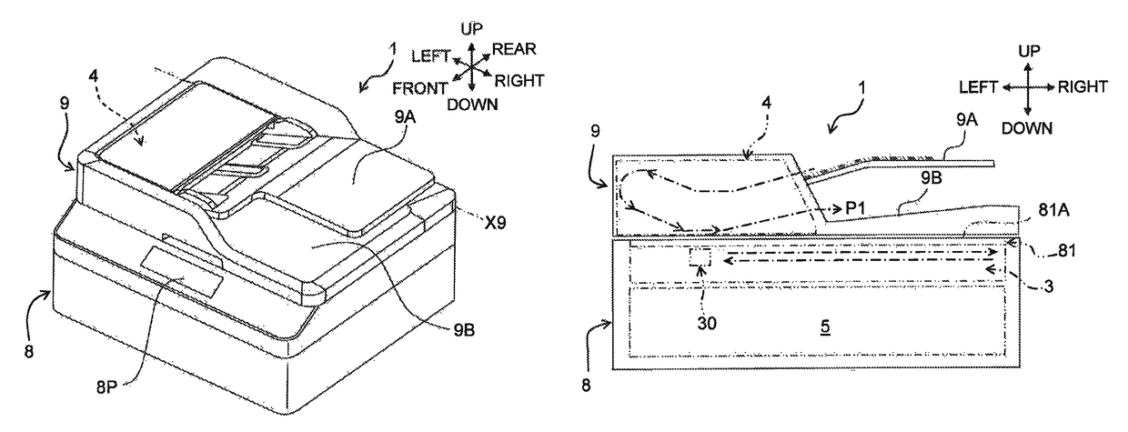
Figure 1 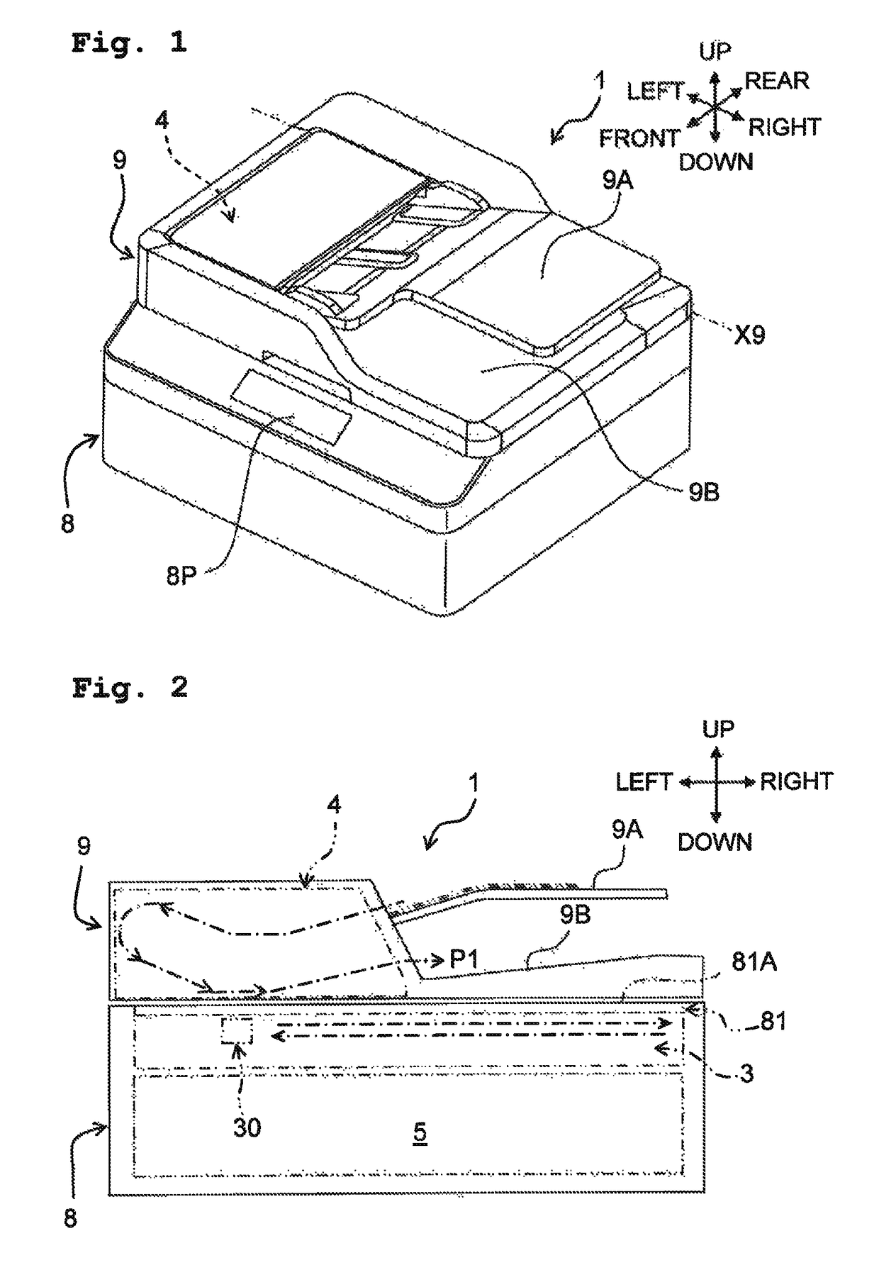
Figure 2 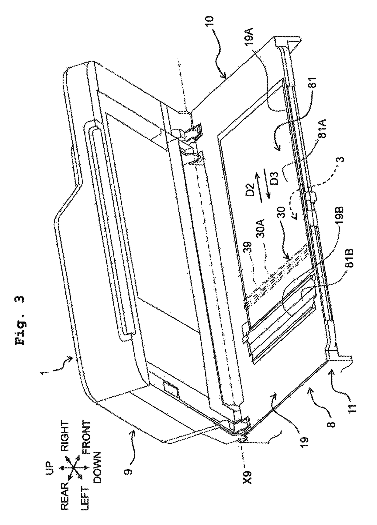
Figure 3
Abstract
Description
CROSS REFERENCE TO RELATED APPLICATION
[0001] The present application claims priority from Japanese Patent Application No. 2016-034575, filed on Feb. 25, 2016, the disclosure of which is incorporated herein by reference in its entirety.BACKGROUND
[0002] Field of the Invention
[0003] The present invention relates to an image reading apparatus.
[0004] Description of the Related Art
[0005] Known as an example of a conventional image reading apparatus is an image reading apparatus that includes a platen glass, a guide member, a line sensor unit, and a coil spring. The platen glass supports a sheet by a front surface of the platen glass. The guide member is capable of reciprocating movement in a sub-scanning direction along a reverse surface of the platen glass, in a state of holding the line sensor unit. The line sensor unit has a reading surface and a plurality of optical sensor elements, and these elements are housed in a box-shaped housing. The reading surface includes a selfoc lens array and ...
Examples
embodiment
Operational Effects of Embodiment
[0120]In the image reading apparatus 1 of the embodiment, as depicted in the likes of FIG. 13, the biasing member 70 is disposed at the front and rear in the housing space 10A. The upper end 71U of the coil spring portion 71 of the biasing member 70 abuts in the first direction D1 on the connecting portion 55 of the transmission member 50, the first contacting portion 51 of the transmission member 50 abuts in the first direction D1 on the lower end of the first wall 41, and the second contacting portion 52 of the transmission member 50 abuts in the first direction D1 on the lower end of the second wall 42. As a result, the biasing force F1 of the coil spring portion 71 of the biasing member 70 is transmitted to the case 40. Moreover, the biasing force F1 of the coil spring portion 71 is transmitted to the case 40 also by the third contacting portion 53 of the transmission member 50 abutting in the first direction D1 on the lower end of the third wall...