A shaving blade cartridge, a shaver comprising such shaving blade cartridge and a method of manufacturing such a shaving blade cartridge

a technology of shaving blades and cartridges, which is applied in the direction of metal working devices, etc., can solve the problems of increasing the manufacturing time and cost increasing the total weight and dimensions of shaving blade cartridges, and complicated manufacturing methods to be implemented. , to achieve the effect of convenient fastening

Active Publication Date: 2016-12-08
BIC VIOLEX SA
View PDF4 Cites 17 Cited by
  • Summary
  • Abstract
  • Description
  • Claims
  • Application Information

AI Technical Summary

Benefits of technology

[0013]With these features, no member or organ specific to the trimming element is needed to fasten the trimming element to the housing. Moreover, the rear element can easily be fastened to the housing without any special tooling. Also, the trimming element is integrated to the shaving blade cartridge on an esthetical way. The trimming element is thus held tightly in position. Moreover, less material is used as raw material for the cover.

Problems solved by technology

The fastening of the additional trimming blade into the housing leads to important manufacturing tolerances and to manufacturing method complicated to be implemented.
The shaving blade cartridge manufacturing time and costs are thus increased.
However, the shaving blade cartridge of WO2005011930 includes the trimming assembly, which is one more piece and which could lead to an increase of the total weight and the dimensions of the shaving blade cartridge.

Method used


Image

  • A shaving blade cartridge, a shaver comprising such shaving blade cartridge and a method of manufacturing such a shaving blade cartridge
  • A shaving blade cartridge, a shaver comprising such shaving blade cartridge and a method of manufacturing such a shaving blade cartridge
  • A shaving blade cartridge, a shaver comprising such shaving blade cartridge and a method of manufacturing such a shaving blade cartridge

Examples


first embodiment

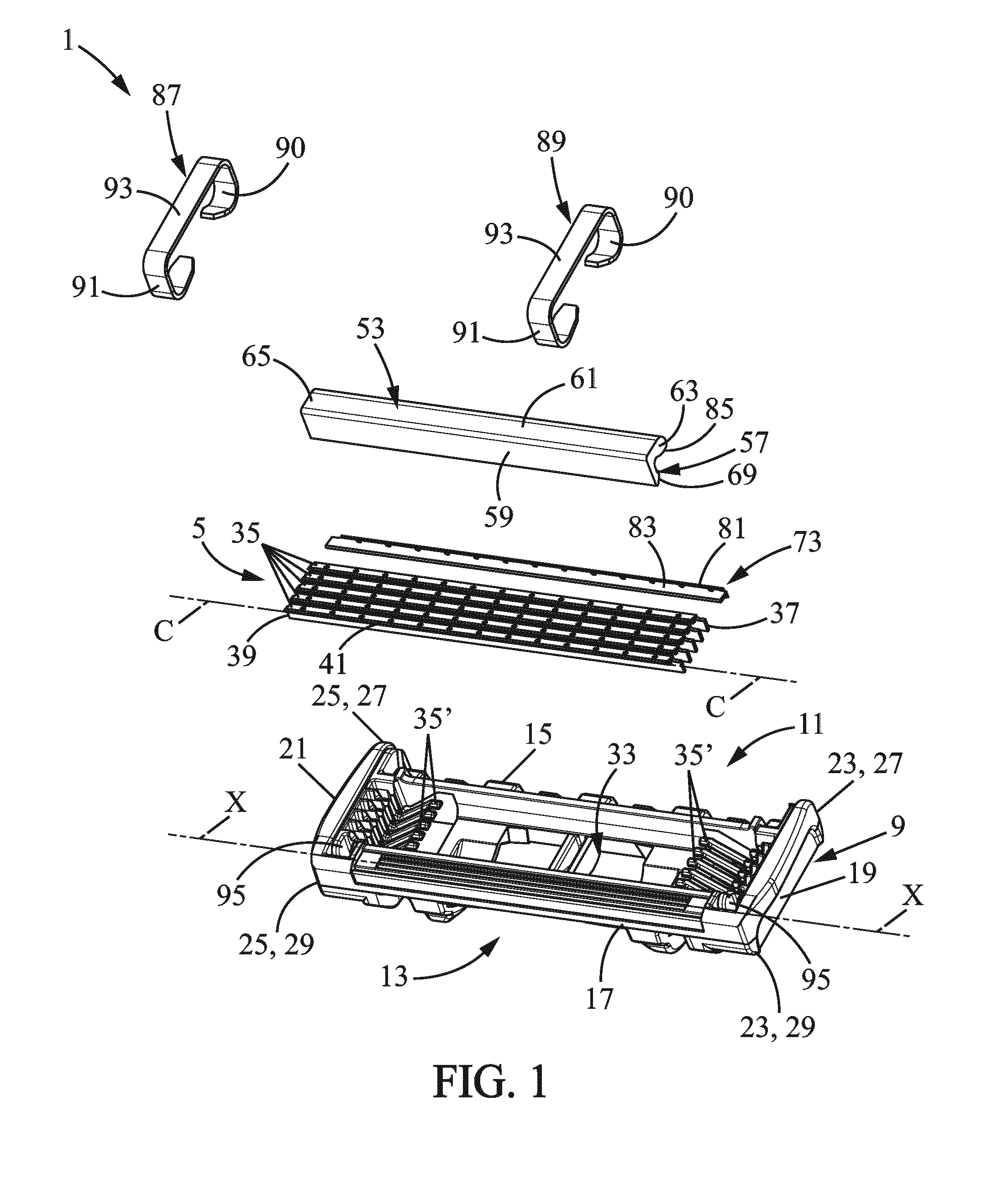
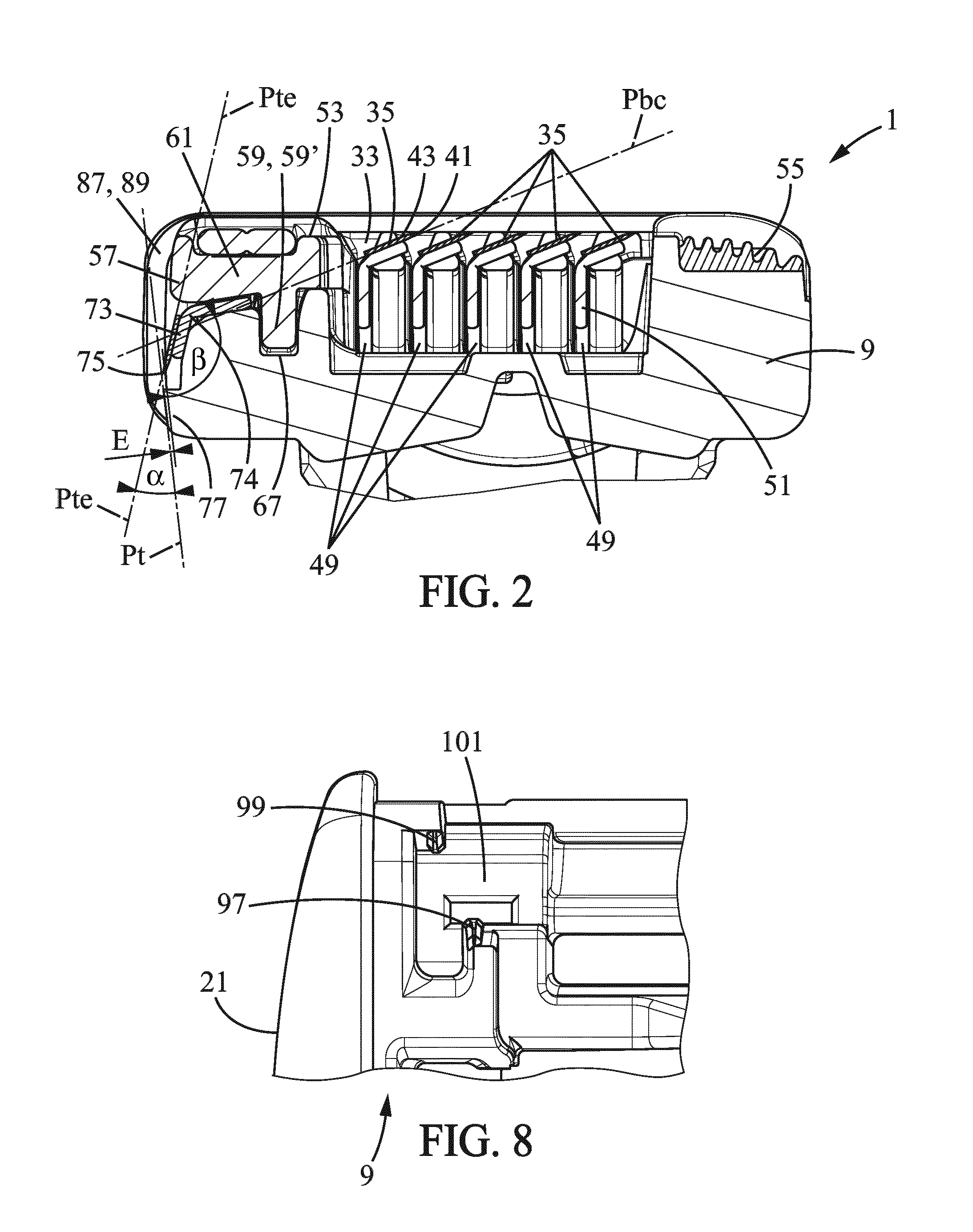
[0079]According to the present invention, as shown in FIGS. 2 and 5, the rear element 57 has a T-shape with two arms 59, 61. The first arm 59 extends transversely from the second arms 61. More precisely, the second arm 61 extends along a direction which is orthogonal to the direction of extension of the first arm 59. An end of the first arm 59 is fixed to a middle portion of the second arm 61.

second embodiment

[0080]According to the present invention, as shown in FIG. 7, the rear element 57 can have a V-shape with two arms 59, 61. The first and second arms 59, 61 extend along a first and second direction. The first and second directions are approximately orthogonal. However, the first and second directions can define an angle different than 90°,which can be an acute or obtuse angle.

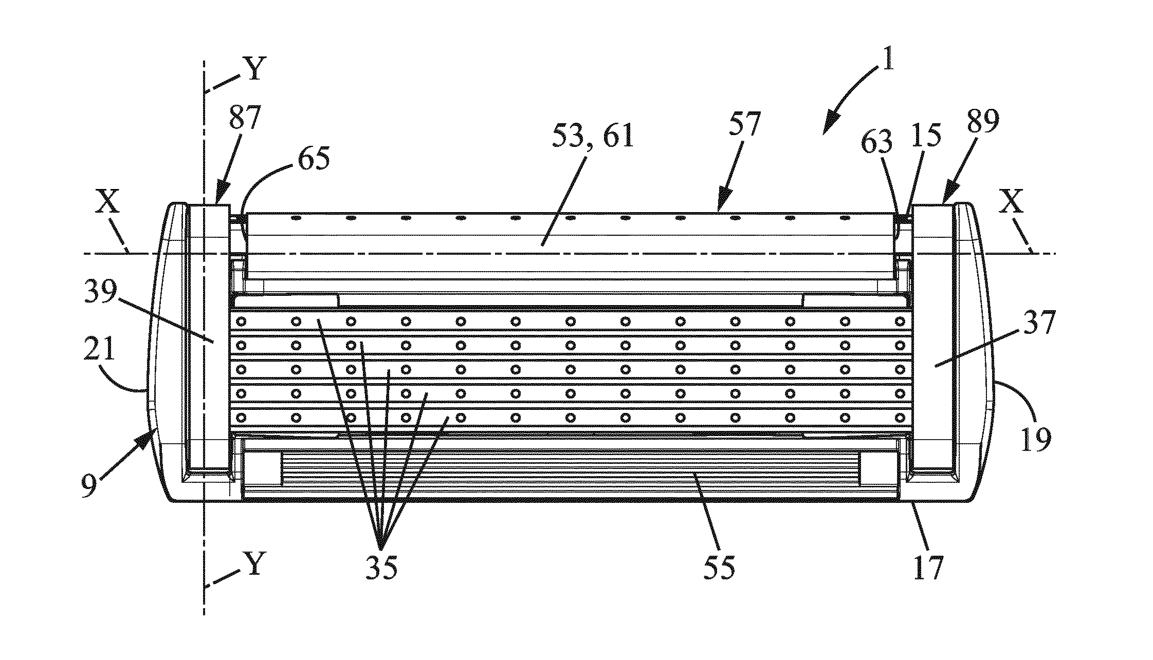
[0081]As shown in FIGS. 2, 3, and 7, the rear element 57 extends along the longitudinal axis X-X between a first and a second free end 63, 65. For example, the first free end 63 of the rear element 57 is located toward the first end 37 of the primary cutting blade 35, whereas the second free end 65 of the rear element 57 is located toward the second end 39 of the primary cutting blade 35. The length of the rear element 57 is smaller than the length of the housing 9 along the longitudinal axis X-X.

[0082]The second arm 61 is preferably provided with the primary cap 53. The primary cap 53 is, for example, provided...


PUM


Abstract

A shaving blade cartridge includes a housing extending along a longitudinal axis having a top side, a bottom side opposite to the top side, and first and second longitudinal sides each extending longitudinally along the longitudinal axis between the top and bottom sides. A primary cutting blade is mounted on the housing between the first and second longitudinal sides, and has a cutting edge. A primary cap is located rearward of the cutting edge. A primary guard is located forward of the cutting edge. A trimming element, mounted on the housing, has a trimming edge. The trimming edge and the cutting edge are opposite one another. The primary cap is provided on a rear element, and the rear element is fitted on the housing. The trimming element is sandwiched between the housing and the primary cap.

Description

[0001]This application is a national stage application of International Application No. PCT / EP2014 / 053880, filed on Feb. 27, 2014, the entire content of which is incorporated herein by reference.FIELD OF THE INVENTION[0002]The embodiments of the present invention relate to shaving blade cartridges, shavers having such shaving blade cartridges, and methods of manufacturing such shaving blade cartridges.BACKGROUND OF THE INVENTION[0003]In particular, the embodiments of the present invention relate to a shaving blade cartridge that includes:[0004]a housing extending along a longitudinal axis having a top side and a bottom side opposite to the top side and first and second longitudinal sides each extending longitudinally along the longitudinal axis between the top and bottom sides,[0005]a primary cutting blade mounted on the housing between the first and second longitudinal sides, and having a cutting edge,[0006]a primary cap, the primary cap being located rearward of the cutting edge,[...

Claims


Application Information

Patent Timeline
Patent Type & Authority Applications(United States)
IPC IPC(8): B26B21/40B26B21/22
CPCB26B21/4031B26B21/4025B26B21/4018B26B21/4043B26B21/4068B26B21/227B26B21/4012B26B21/222B26B21/565B26B21/40
Inventor BOZIKIS, IOANNISGEORGAKIS, GEORGIOSPAPAGEORGIS, PHAEDONEFTHIMIADIS, DIMITRIOSDAVOS, VASILEIOSKOULOURIAS, GEORGIOSPOLYCHRONIDIS, PETROS
Owner BIC VIOLEX SA
Why Eureka
Try Eureka