
Restriction plug element and method

Inactive Publication Date: 2016-12-08
GEODYNAMICS
View PDF12 Cites 16 Cited by
  • Summary
  • Abstract
  • Description
  • Claims
  • Application Information

AI Technical Summary

Benefits of technology

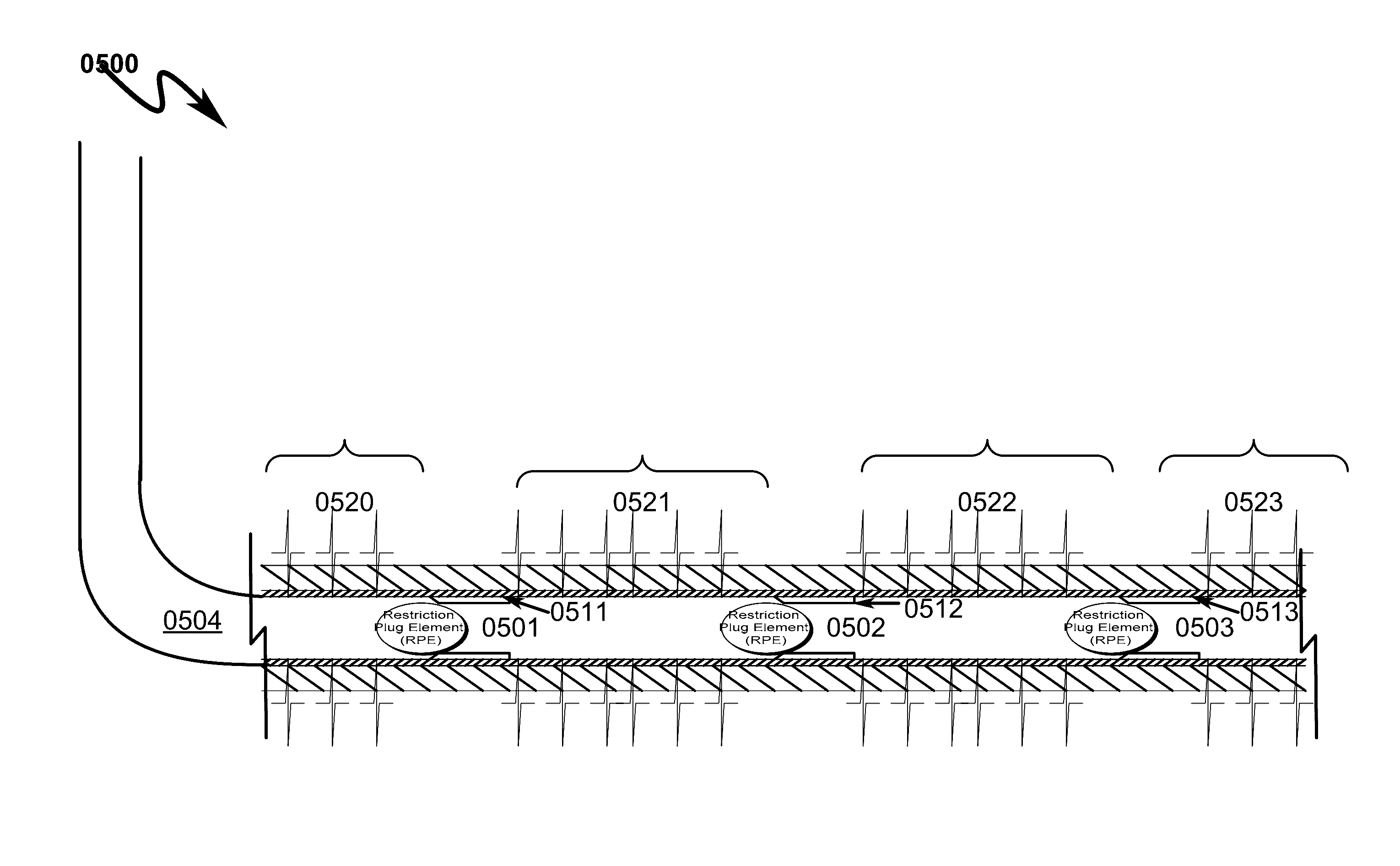
This patent aims to solve two problems: the first is how to position and remove restrictive elements without causing damage or delay, and the second is how to prevent premature preset conditions that may prevent further wellbore operations.

Problems solved by technology

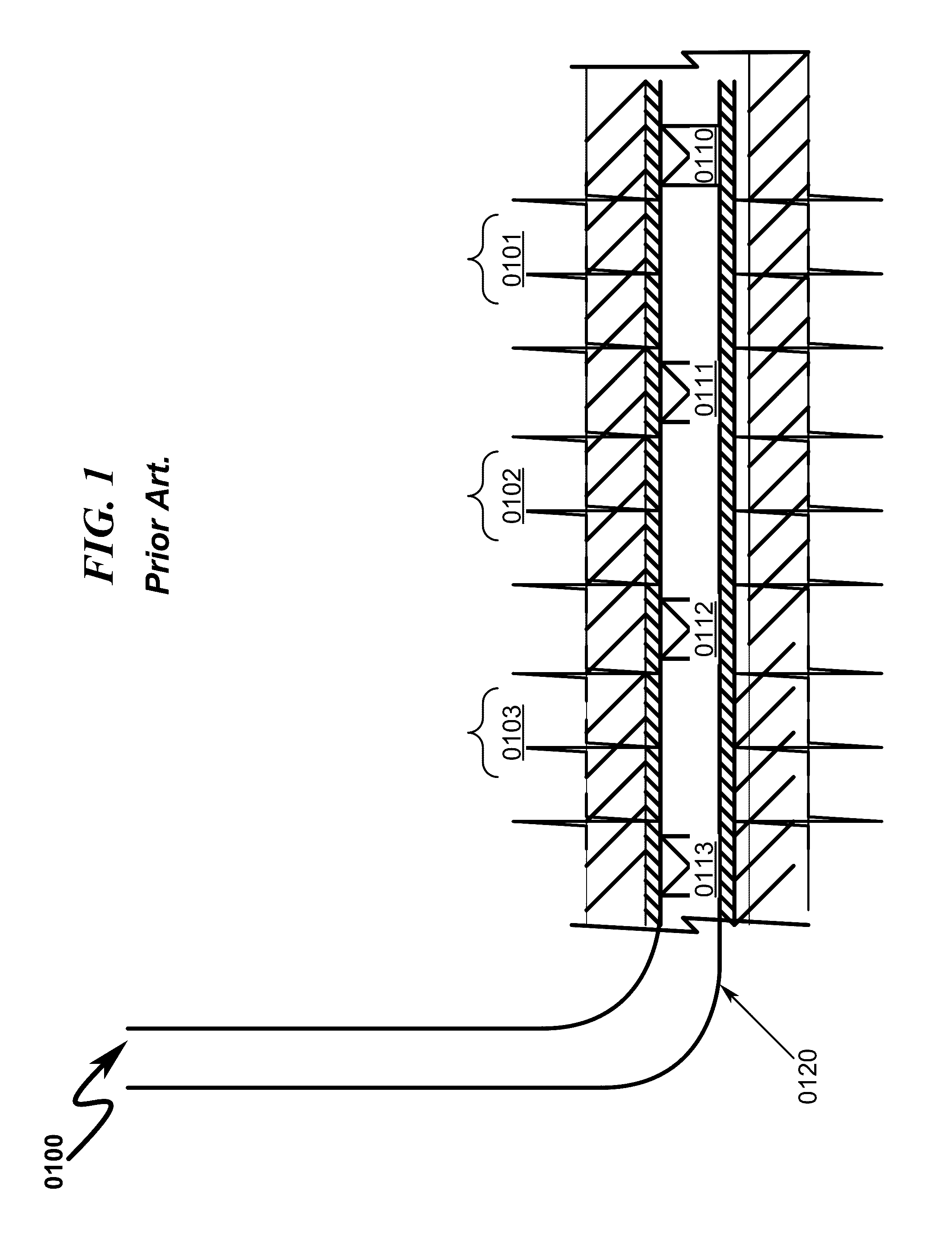
Additionally, frac plugs can be inadvertently set at undesired locations in the wellbore casing creating unwanted constrictions.
The constrictions may latch wellbore tools that are run for future operations and cause unwanted removal process.
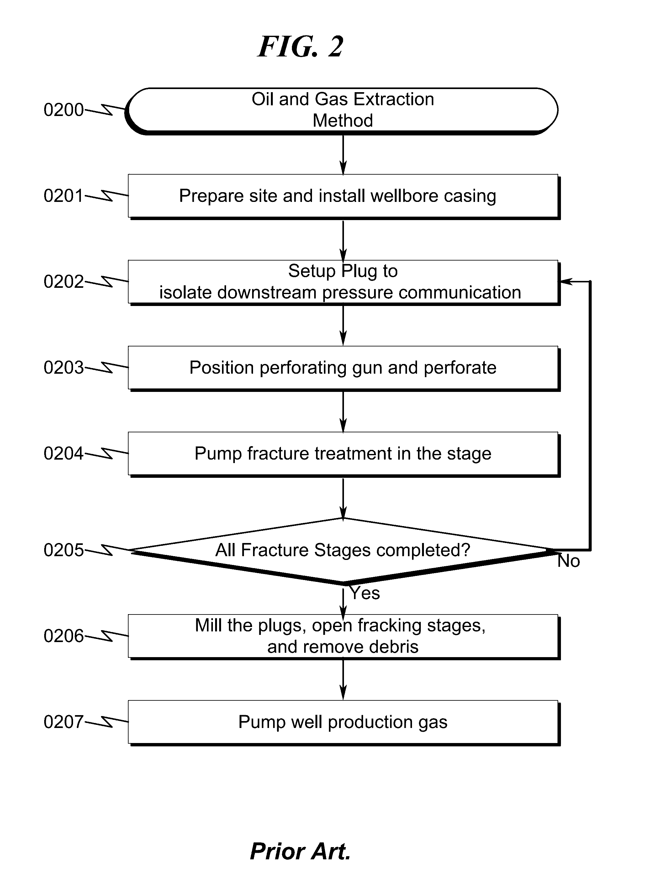
Each trip is time consuming and expensive.
In addition, the process of drilling and milling the plugs creates debris that needs to be removed in another operation.
The prior art as detailed above suffers from the following deficiencies:Prior art systems do not provide for positioning a ball seat at a desired location after a wellbore casing has been installed, without depending on a predefined sleeve location integral to the wellbore casing to position the plug.Prior art systems do not provide for isolating multiple hydraulic fracturing zones without the need for a milling operation.Prior art systems do not provide for positioning restrictive elements that could be removed in a feasible, economic, and timely manner.Prior art systems do not provide for setting larger inner diameter sleeves to allow unrestricted well production fluid flow.Prior art systems cause undesired premature preset conditions preventing further wellbore operations.
While some of the prior art may teach some solutions to several of these problems, the core issue of isolating hydraulic fracturing zones without the need for a milling operation has not been addressed by prior art.

Method used


Image

  • Restriction plug element and method
  • Restriction plug element and method
  • Restriction plug element and method

Examples


Embodiment Construction

[0093]While this invention is susceptible of embodiment in many different forms, there is shown in the drawings and will herein be described in detailed preferred embodiment of the invention with the understanding that the present disclosure is to be considered as an exemplification of the principles of the invention and is not intended to limit the broad aspect of the invention to the embodiment illustrated.

[0094]The numerous innovative teachings of the present application will be described with particular reference to the presently preferred embodiment, wherein these innovative teachings are advantageously applied to the particular problems of a wellbore plug isolation system and method. However, it should be understood that this embodiment is only one example of the many advantageous uses of the innovative teachings herein. In general, statements made in the specification of the present application do not necessarily limit any of the various claimed inventions. Moreover, some sta...


PUM


Abstract

A restriction plug element and method for positioning plugs to isolate fracture zones in a horizontal, vertical, or deviated wellbore is disclosed. The restriction plug element includes a partial hollow passage with an interior end. The partial passage enables the plug element to seat in a restriction sleeve member during treatment and subsequently degrade to form a complete hollow passage. The complete flow channel dissolves or degrades not only the outside but also the inside of the wall of the restriction plug element. Initially the flow is restricted by the closed end in the partial hollow passage and over time the flow channel opens up by degradation and allows fluid to pass through in either direction. During back flow in the well new fluid is circulated into the well and the restriction plug element continues to degrade.

Description

CROSS REFERENCE TO RELATED APPLICATIONS[0001]This application is a continuation-in-part of U.S. application Ser. No. 14 / 721,784, filed May 26, 2015, which claims the benefit of U.S. Provisional No. 62 / 081,399, filed Nov. 18, 2014, which is also a continuation-in-part of U.S. application Ser. No. 14 / 459,042, filed Aug. 13, 2014, now U.S. Pat. No. 9,062,543, the disclosures of which are fully incorporated herein by reference.FIELD OF THE INVENTION[0002]The present invention generally relates to oil and gas extraction. Specifically, the invention attempts to isolate fracture zones through selectively positioning restriction elements within a wellbore casing.[0003]PRIOR ART AND BACKGROUND OF THE INVENTIONPrior Art Background[0004]The process of extracting oil and gas typically consists of operations that include preparation, drilling, completion, production and abandonment.[0005]Preparing a drilling site involves ensuring that it can be properly accessed and that the area where the rig ...

Claims


Application Information

Patent Timeline
IPC IPC(8): E21B43/26E21B33/12E21B43/14E21B29/02
CPCE21B34/063E21B43/14E21B43/26
Inventor HARDESTY, JOHN T.WROBLICKY, MICHAEL D.
Owner GEODYNAMICS
Learn More