Image determining method and object coordinate computing apparatus

a computing apparatus and image technology, applied in the field of image determining method and object coordinate computing apparatus, can solve the problem of difficult selection of the most suitable brightness threshold value, and achieve the effect of more accurate determining mechanism and more accurate displacement detection

Active Publication Date: 2016-12-15
PIXART IMAGING INC
View PDF3 Cites 1 Cited by
  • Summary
  • Abstract
  • Description
  • Claims
  • Application Information

AI Technical Summary

Benefits of technology

[0010]In view of above-mentioned embodiments, the present invention provides an image determining method for determining specific image pixels or object pixels, an object coordinate computing method and an object coordinate computing apparatus, according to brightness and parameters besides brightness. By this way, the prior art issue that only brightness is utilized for determining can be avoided. Besides, different conditions can be set based on different object types and the size for caught images, such that the determining mechanism can be more accurate and can be set unlimitedly. Furthermore, the gravity center of the object can be moved downward if the gravity center is computed according to the image determining mechanism of the present invention. By this way, the gravity center matches the habit for a user while handling a remote controller, such that the displacement detecting can be more accurate.

Problems solved by technology

Also, the size, location and brightness values of different specific images caused by different objects are all different, thus a most suitable brightness threshold value is hard to select.

Method used


Image

  • Image determining method and object coordinate computing apparatus
  • Image determining method and object coordinate computing apparatus
  • Image determining method and object coordinate computing apparatus

Examples


first embodiment

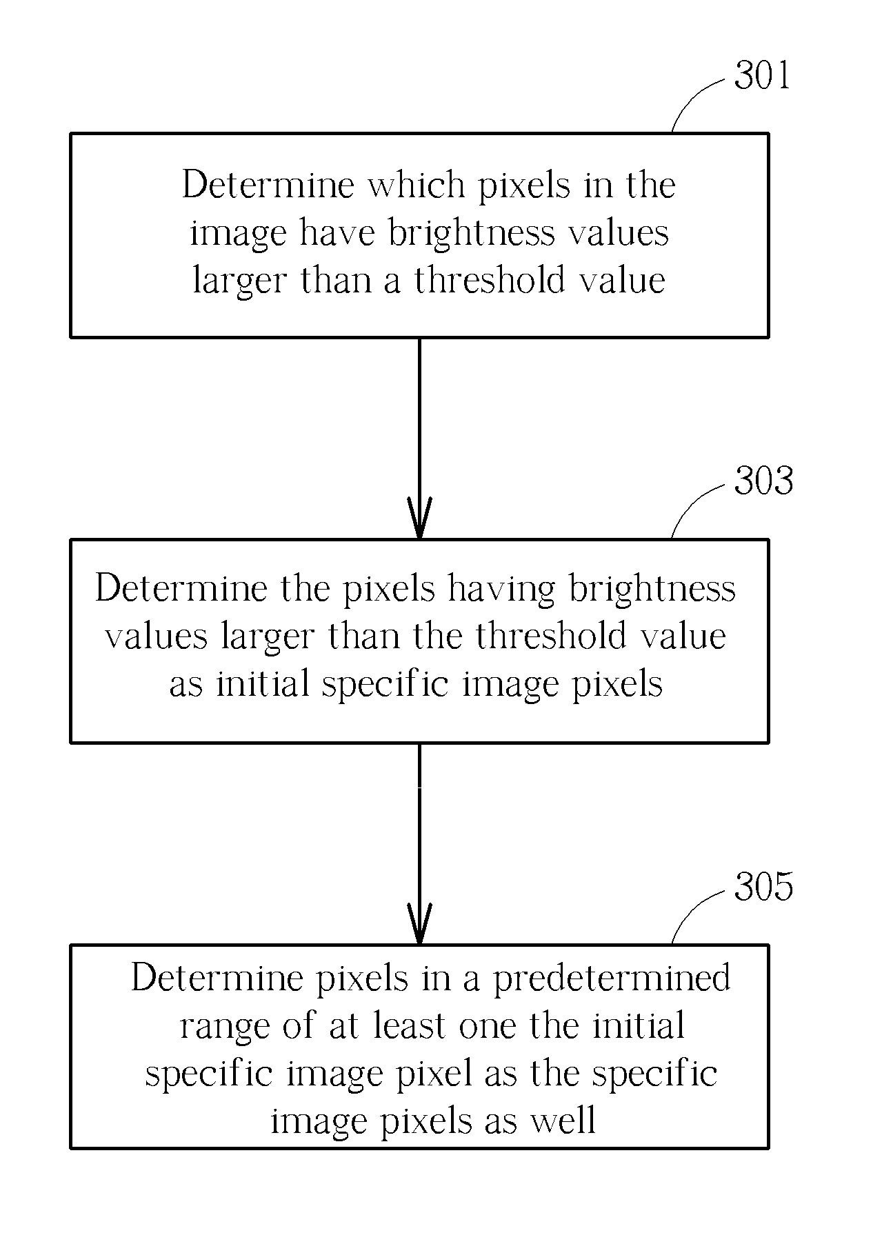
[0020]The image determining method shown in FIG. 3 can be acquired shown in FIG. 2, which includes the following steps:

Step 301

[0021]Determine which pixels in the image have brightness values larger than a threshold value.

Step 303

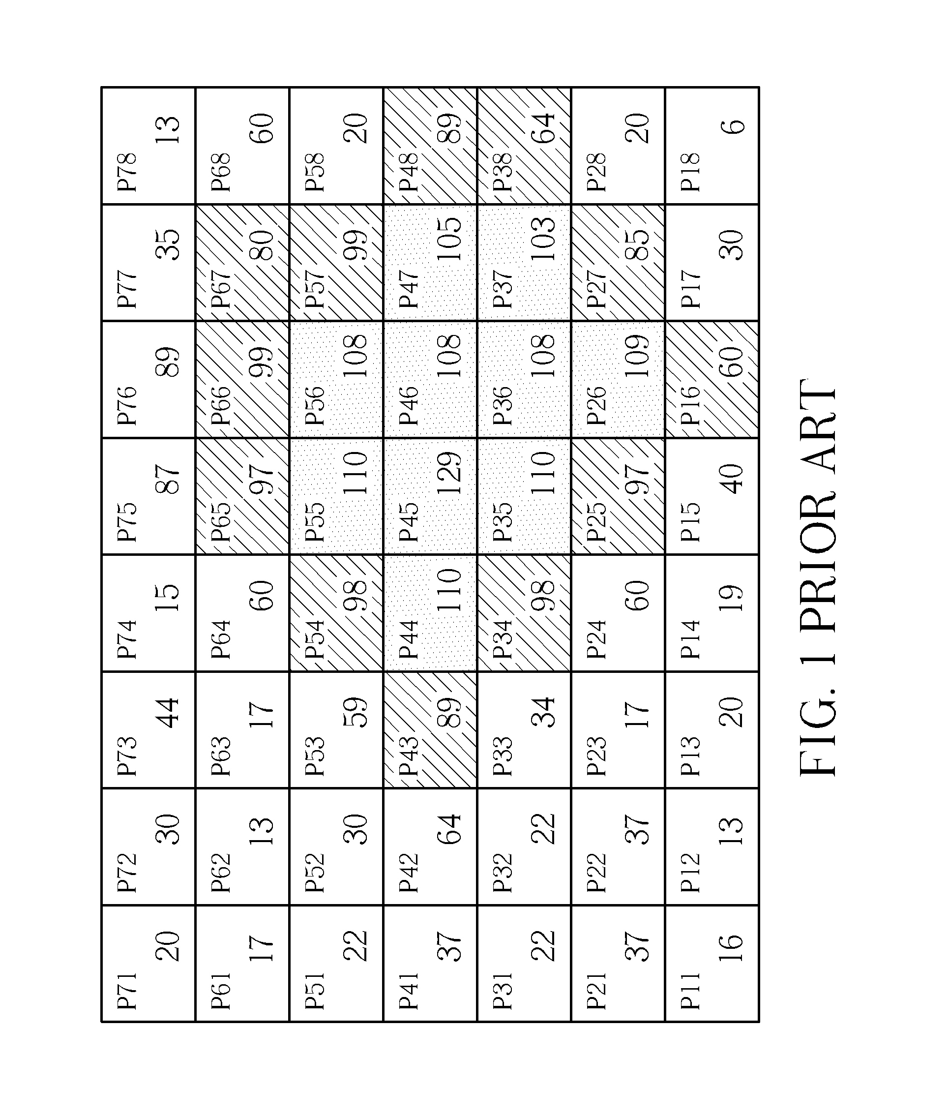
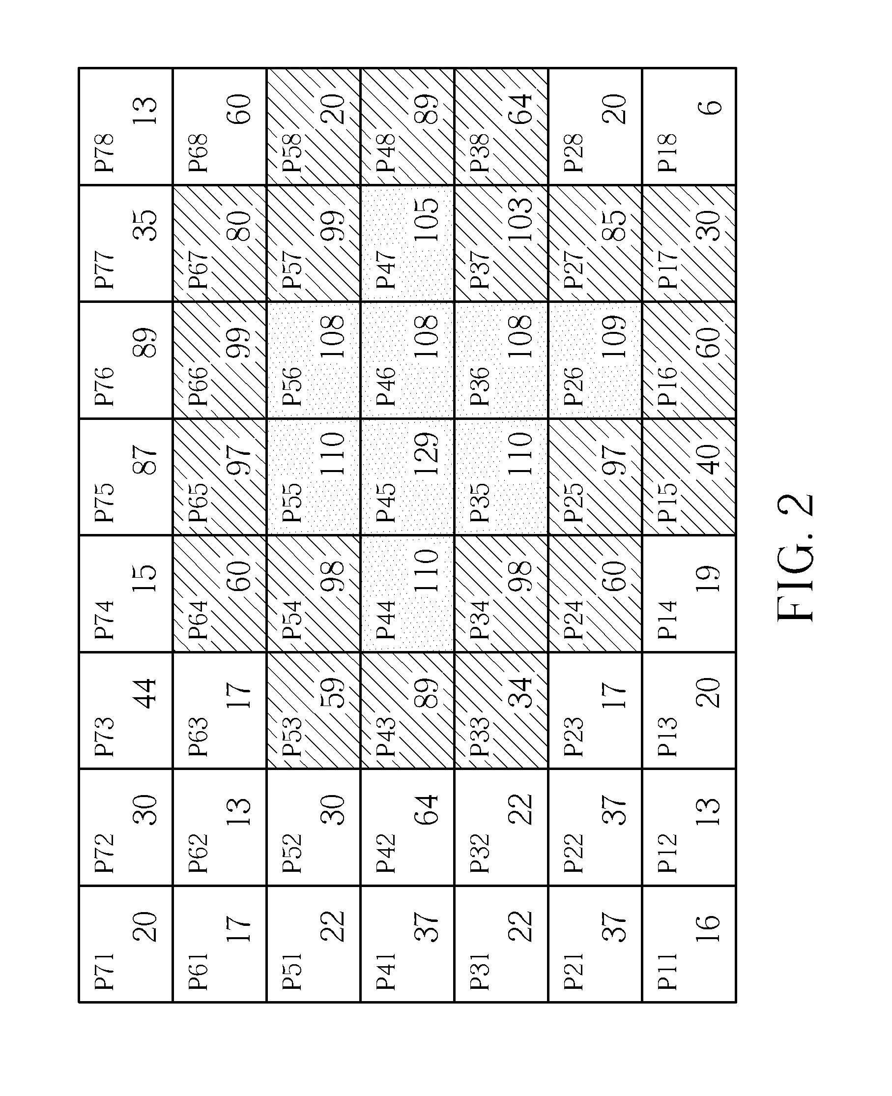
[0022]Determine the pixels having brightness values larger than the threshold value as initial specific image pixels (Such as pixels P26, P35-P36, P44-P47 and P55-P66 in FIG. 2).

Step 305

[0023]Determine pixels in a predetermined range of at least one the initial specific image pixel as the specific image pixels as well. In one example, the predetermined range is a 3×3 pixel matrix such that the pixels P15-P17, P24-P25, P27, P33-P34, P37-P38, P43, P48, P53-P54. P57-P58 and P64-P67, which are not initial specific image pixels, are also determined to be specific image pixels.

[0024]Other detail steps can be acquired according to the embodiment shown in FIG. 2, thus are omitted for brevity here.

second embodiment

[0025]In the second embodiment shown in FIG. 4, pixels of at least one raw in an image are scanned in turn and determined which pixels have brightness values larger than a threshold value. In FIG. 4, the direction for scanning is downward. That is, pixels P71-P78 are scanned first, then the pixels P61-P68 are scanned, then the pixels P61P68 are scanned . . . and so on. If anyone row of the image (the first one row L1 in this embodiment) is determined to include at least one pixel having a brightness value larger than a threshold value such as pixels P55, P56 (named first row specific image pixels), the first row specific image pixels are determined as specific image pixels and a specific image range W1 is defined according to the first row specific image pixels. In one embodiment, the leftmost pixel and the rightmost pixel of the first row specific image pixels are utilized to define edges of the specific image range W1, but it is not limited. Also, the image pixels in the specific ...


PUM


Abstract

An image determining method for scanning an image and determining specific image pixels of a specific image. The method comprises: determining at least one pixel in a first row having brightness value larger than a threshold value as the specific image pixel; defining a leftmost pixel and a rightmost pixel of the specific image pixel in the first row as a leftmost edge and a rightmost edge of a first specific image range; and defining a second specific image range in a second row of the image, which is next to the first row. Column positions of a leftmost edge and a rightmost edge of the second specific image range are respectively the same with column positions of the leftmost edge and the rightmost edge of the first specific image range. Via this method, the determining for the specific image pixels is more accurate.

Description

CROSS REFERENCE TO RELATED APPLICATIONS[0001]This is a continuation application of U.S. patent application Ser. No. 13 / 789,591, filed on Mar. 07, 2013 and included herein by reference.BACKGROUND OF THE INVENTION[0002]1. Field of the Invention[0003]The present invention relates to an image determining method and an object coordinate computing apparatus, and particularly relates to an image determining method and an object coordinate computing apparatus, which utilize both brightness and conditions besides brightness to determine the predetermined image pixel or the object pixel.[0004]2. Description of the Prior Art[0005]FIG. 1 is a schematic diagram illustrating a prior art image determining method for determining an object coordinate in an image. FIG. 1 is a gray level diagram of an image (i.e. an brightness diagram of an image), which is a 7×8 matrix having 7×8 pixels P11-P78. The image includes a specific image generated by an object (in this example, a light source). Specific ima...

Claims


Application Information

Patent Timeline
Patent Type & Authority Applications(United States)
IPC IPC(8): G06K9/62G06K9/46G06K9/34
CPCG06K9/62G06K9/4604G06K9/4642G06K9/342G06V10/267G06T7/136G06T7/11G06F18/00G06F18/22
Inventor LIANG, CHIA-CHEUNYANG, SHU-SIANKO, YI-HSIEN
Owner PIXART IMAGING INC
Why Eureka
Try Eureka