Mobile projection system for scaling and orientation of surfaces surveyed by an optical measuring system

a projection system and optical measuring technology, applied in the field of mobile projection system, can solve the problems of needing work in hazardous areas and costing additional effort such as tim

Inactive Publication Date: 2013-09-03
3G SOFTWARE & MEASUREMENT
View PDF7 Cites 1 Cited by
  • Summary
  • Abstract
  • Description
  • Claims
  • Application Information

AI Technical Summary

Benefits of technology

[0012]It is an object of the present invention to provide a proper scaling and orientation mechanism for surveying of surfaces e.g. rock surfaces, terrain surfaces, or natural or artificial object surfaces.

Problems solved by technology

This may need work in hazardous areas.
The placement of the marker elements may require working in hazardous areas and may cost additional efforts such as time.

Method used


Image

  • Mobile projection system for scaling and orientation of surfaces surveyed by an optical measuring system
  • Mobile projection system for scaling and orientation of surfaces surveyed by an optical measuring system
  • Mobile projection system for scaling and orientation of surfaces surveyed by an optical measuring system

Examples


Embodiment Construction

[0056]The illustrations in the drawings are schematical. In different drawings similar or identical elements are provided with the same reference signs. The view in the figures is schematical and not fully scaled.

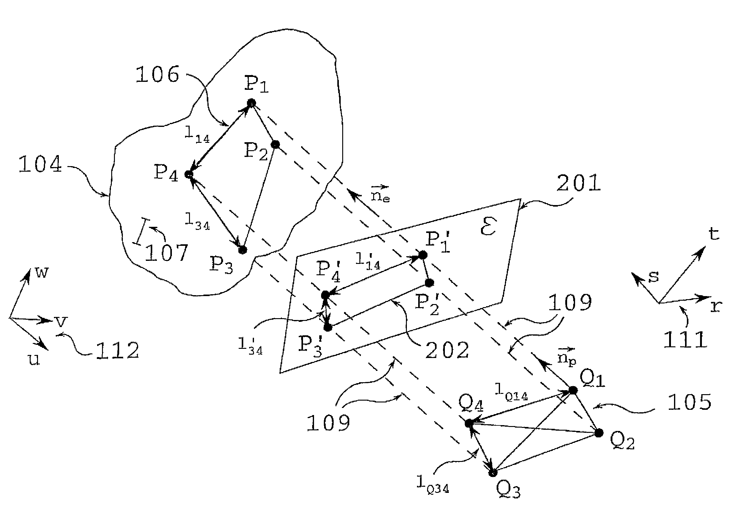
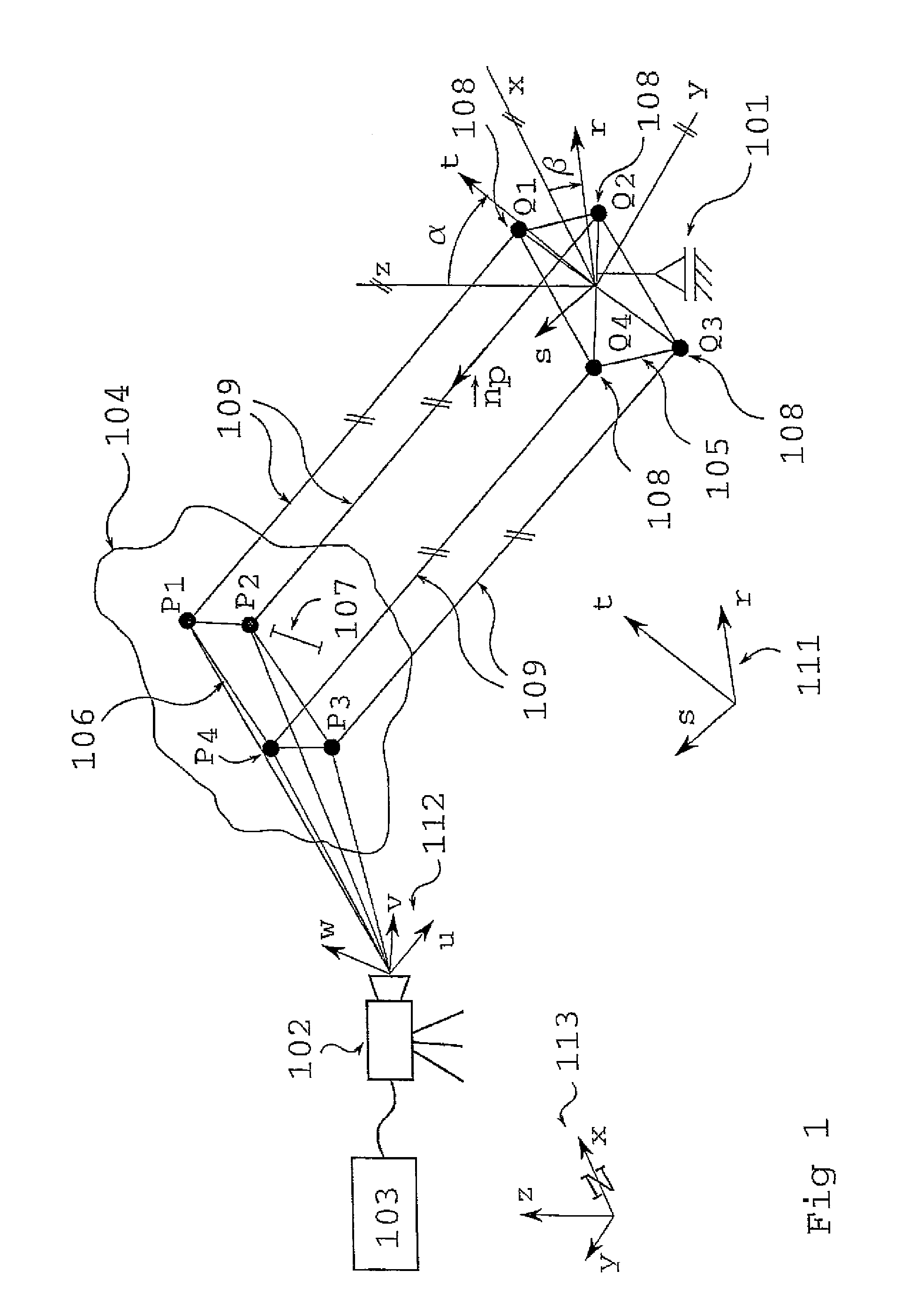
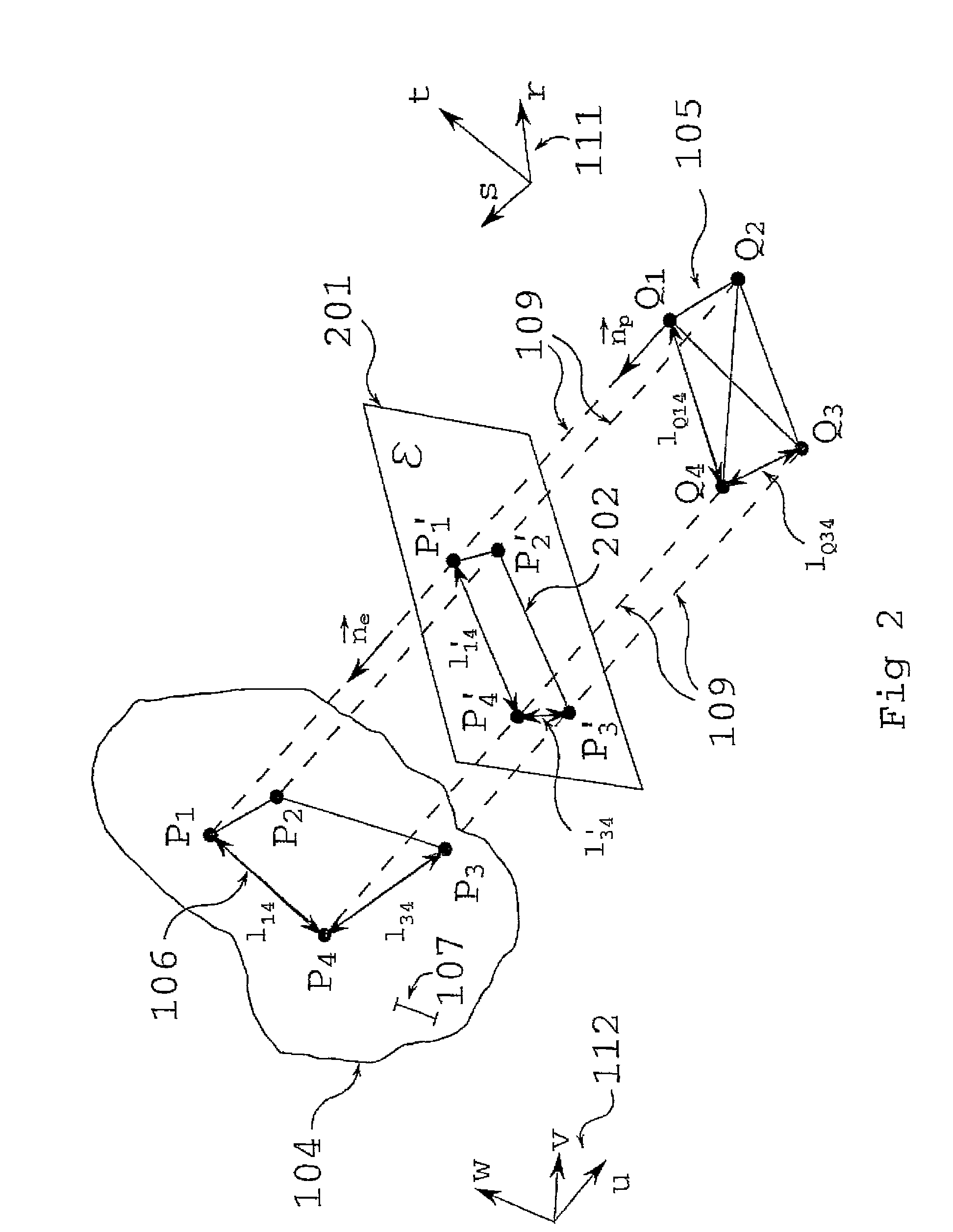
[0057]FIG. 1 illustrates a device for surveying a surface 104 in the real world coordinate system 111. The device comprises a pattern projecting unit 101, an optical measurement system 102 and a processing unit 103. The pattern projecting unit 101 is adapted for projecting a predefined pattern 105 onto the surface 104. The optical measurement system 102 is adapted for determining positional and image data of a projected pattern 106 on the surface 104, wherein the image data are indicative of the predefined pattern 105 in a measuring coordinate system 112. The processing unit 103 is adapted for determining transformation data based on the predefined pattern 105 and the determined positional and image data of the projected pattern 106. The transformation data allow a transfor...


PUM


Abstract

The present invention describes a device for surveying a surface (104) in a real world coordinate system (111). The device comprises a pattern projecting unit (101) adapted for projecting a predefined pattern (105) onto the surface (104), an optical measurement system (102) adapted for determining positional and image data of a projected pattern (106) on the surface (104), wherein the positional and image data are indicative of the predefined pattern (105) in a measuring coordinate system (112), and a processing unit (103) adapted for determining transformation data based on the predefined pattern (105) and the determined positional and image data of the projected pattern (106). The transformation data allow a transformation between the real world coordinate system (111) and the measuring coordinate system (112) to thereby survey the surface (104).

Description

REFERENCE TO RELATED APPLICATION[0001]This application claims the benefit of the filing date of the European Patent Application 09153316.6, filed Feb. 20, 2009, the disclosure of which application is hereby incorporated herein by reference.FIELD OF THE INVENTION[0002]The invention relates to a device for surveying a surface and to a method of surveying a surface. Moreover, the present invention relates to a computer-readable medium in which a computer program for surveying a surface in a real world coordinate system is stored and to a program element for surveying a surface in the real world coordinate system.BACKGROUND OF THE INVENTION[0003]Underground construction works in rock require knowledge on the rock mass in order to take account for the actual conditions. One important source of information is related to geological mapping. Among others geological mapping includes gathering data on (i) geometric properties of the rock surface as well as (ii) spatial orientation information...

Claims


Application Information

Patent Timeline
Patent Type & Authority Patents(United States)
IPC IPC(8): G01B11/24
CPCG01C15/004
Inventor LENZ, GUNTHERGAICH, ANDREAS
Owner 3G SOFTWARE & MEASUREMENT
Why Eureka
Try Eureka