
Eureka
For R&D, Eureka makes reading and utilizing patents & technical documents easy.
Eureka AIR
Designed for self-driven R&D workflows. Generate viable solutions, solve complex R&D challenges, empower your innovation with AI.

Eureka Materials
Designed for material experts only. Revolutionize your material R&D, from search, analyze, to developing new materials.

TechResearch
Generate reliable direction feasibility study reports for your R&D in just a few steps.

TechSeek
Discover and master advanced knowledge NOW. Basics, ideas, possibilities, all at once.

TechMind
As an expert in R&D Theories, TechMind can generates customized viable solutions instantly.

TechRisk
Analyze your overall solution with one click, know your potential R&D risks in advance.

TechMonitor
Get weekly tech updates, stay abreast of the latest tech innovations and key insights.
Hot melt insulation fixing plate as well as a plug and a socket using that hot melt insulation fixing plate
- Summary
- Abstract
- Description
- Claims
- Application Information
AI Technical Summary
Benefits of technology
Problems solved by technology
Method used
Image

Examples
first embodiment
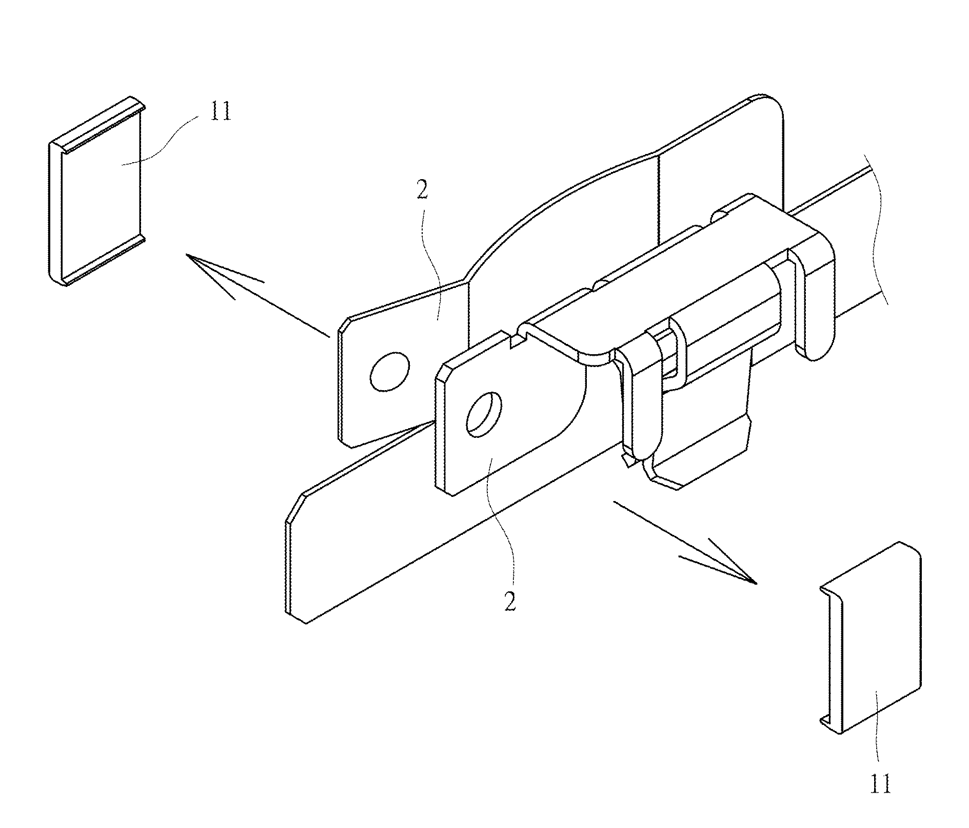
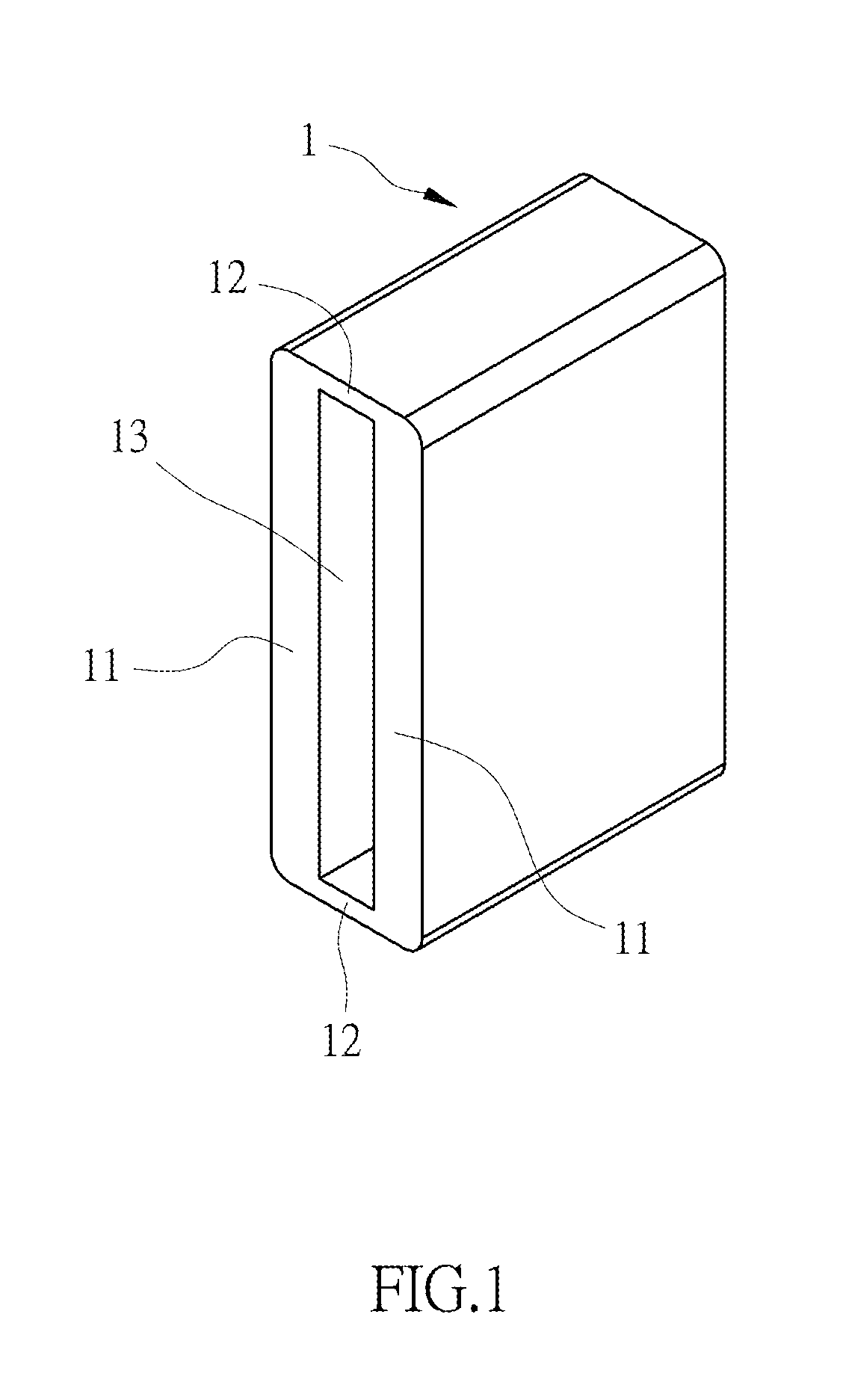
[0054]Please refer to FIG. 1 for the present invention. An insulation fixing plate of the present embodiment comprises an insulative annular sleeve 1 which is provided with two opposite stopping parts 11 and two opposite connecting parts 12 that connect the two stopping parts 11. The two stopping parts 11 and the two connecting parts 12 commonly define a holding space 13. The thickness of the two connecting parts 12 is between 0.1 cm and 1.2 cm, and is 0.7 cm for the present embodiment. In addition, the thickness of the stopping part 11 is not smaller than the thickness of any one of the two connecting parts 12.
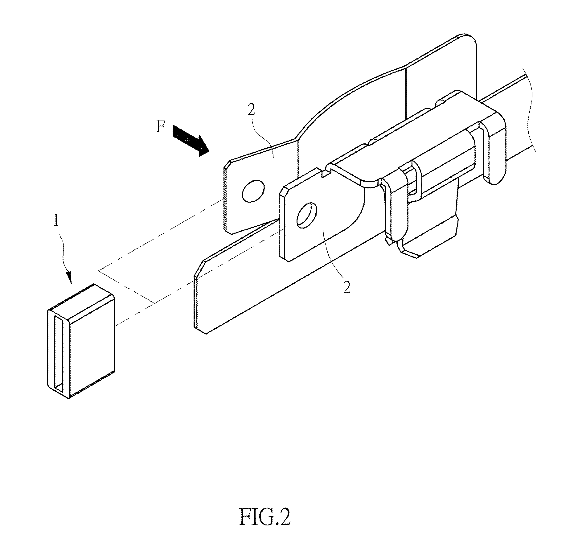
[0055]Referring to FIGS. 2 to 5, the insulative annular sleeve 1 is sheathed on two conductive members 2 of the protected circuit, wherein the two conductive members 2 are separated and do not contact with each other in an initial state. First, an external force F is applied to enable the two conductive members 2 to approach to and contact with each other, and then, the insul...
fourth embodiment
[0061]Please refer to FIG. 15 for a An insulation fixing plate of the present embodiment comprises an insulative annular sleeve 1C which is provided with two opposite stopping parts 11C and two opposite connecting parts 12C that connect the two stopping parts 11C. The two stopping parts 11C and the two connecting parts 12C commonly define a holding space 13C. The thickness of the two connecting parts 12C is between 0.1 cm and 1.2 cm, and is 0.7 cm for the present embodiment. The thickness of each stopping part 11C is not smaller than the thickness of any one of the two connecting parts 12C. In the present embodiment, a middle section of each connecting part 12C is formed with an indented concave part 14C which faces the other connecting part 12C. The thickness at the location of the concave part 14C of the connecting part 12C is between 0.1 cm and 1.2 cm. It should be pointed out that in this embodiment, the configuration of the two connecting parts 12C can change freely, as long a...
PUM
 Abstract
Description
Claims
Application Information
 - R&D Engineer
- R&D Manager
- IP Professional
- Industry Leading Data Capabilities
- Powerful AI technology
- Patent DNA Extraction
Browse by: Latest US Patents, China's latest patents, Technical Efficacy Thesaurus, Application Domain, Technology Topic, Popular Technical Reports.
© 2024 PatSnap. All rights reserved.Legal|Privacy policy|Modern Slavery Act Transparency Statement|Sitemap|About US| Contact US: help@patsnap.com