Supercharge Your Innovation With Domain-Expert AI Agents!

Relative position measurement

a relative position and sensor technology, applied in the field of feedback sensors, can solve the problems of unreliable configuration, and affecting the reliability of the system

Active Publication Date: 2016-12-29
GENERAL ELECTRIC CO
View PDF4 Cites 4 Cited by
  • Summary
  • Abstract
  • Description
  • Claims
  • Application Information

AI Technical Summary

Benefits of technology

The invention has certain benefits and advantages that can be understood by reading the description or through practice. The technical effects of the invention allow for certain improvements and innovation.

Problems solved by technology

However, such a configuration may weaken the one or more shafts or require additional bolstering of the one or more shafts to accommodate the elongated slots or openings.
However, such a configuration can be unreliable.

Method used


Image

  • Relative position measurement
  • Relative position measurement
  • Relative position measurement

Examples


Embodiment Construction

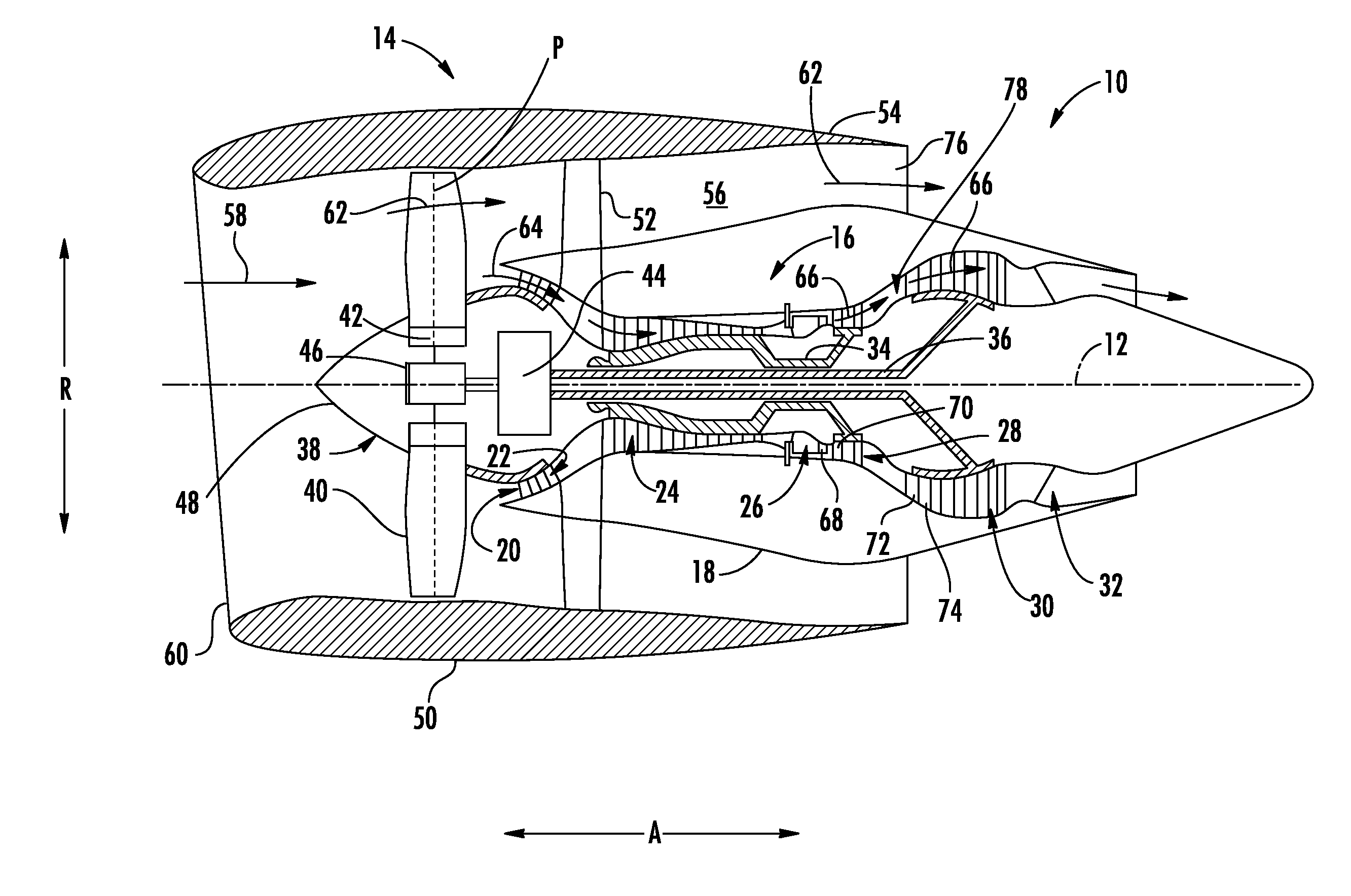
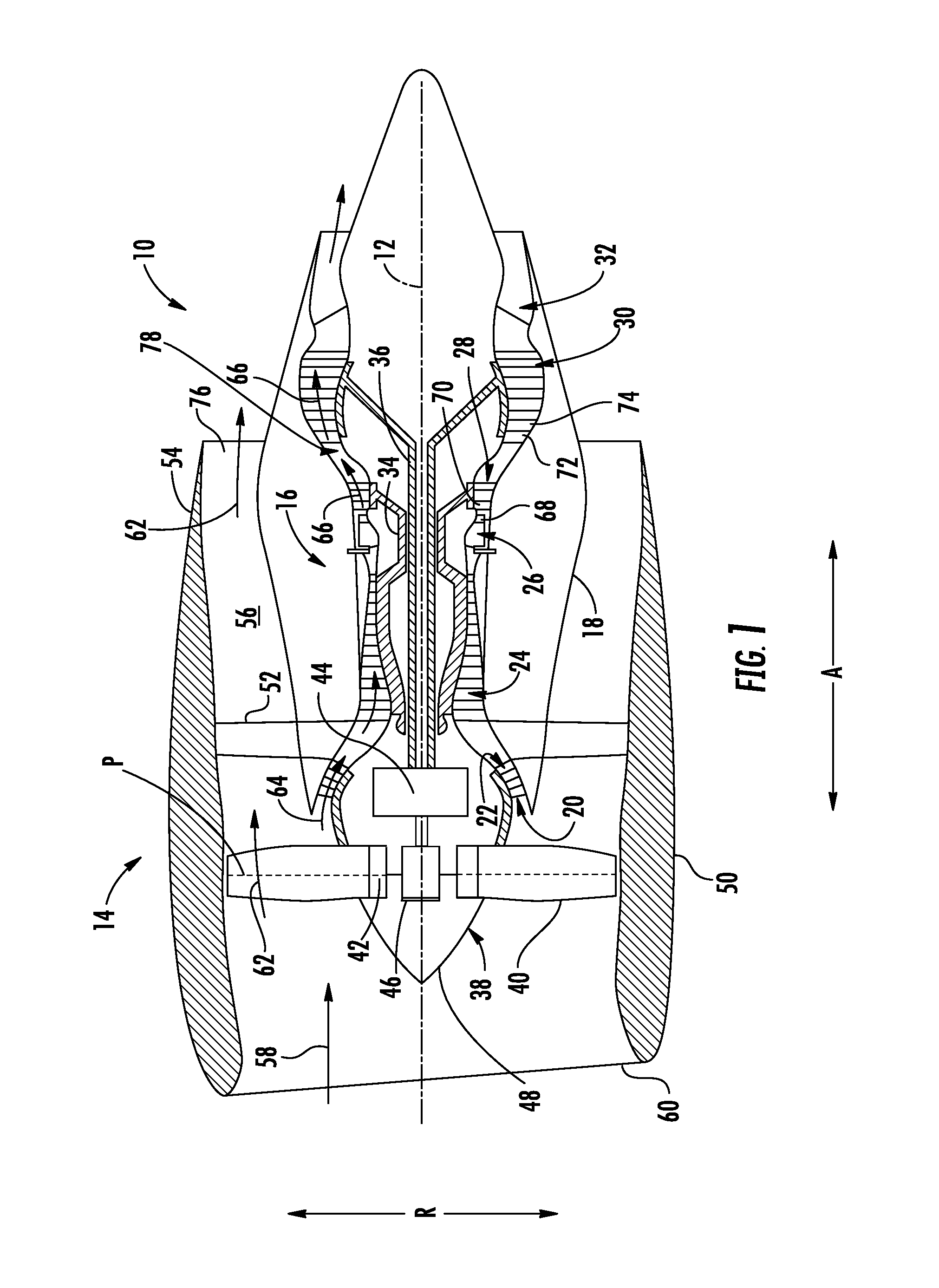
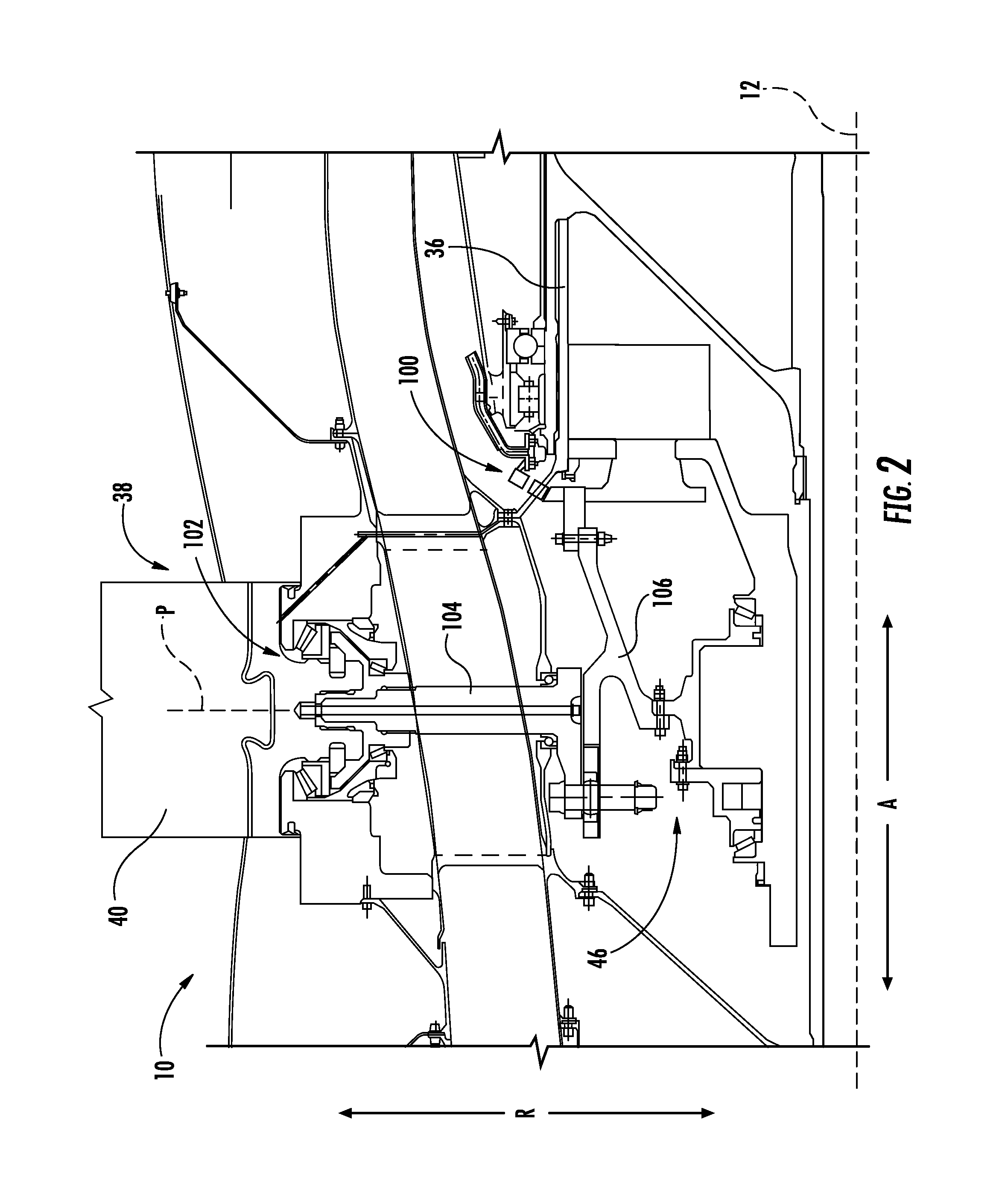
[0019]Reference will now be made in detail to present embodiments of the invention, one or more examples of which are illustrated in the accompanying drawings. The detailed description uses numerical and letter designations to refer to features in the drawings. Like or similar designations in the drawings and description have been used to refer to like or similar parts of the invention. As used herein, the terms “first”, “second”, and “third” may be used interchangeably to distinguish one component from another and are not intended to signify location or importance of the individual components.

[0020]Referring now to the drawings, wherein identical numerals indicate the same elements throughout the figures, FIG. 1 is a schematic cross-sectional view of a gas turbine engine in accordance with an exemplary embodiment of the present disclosure. More particularly, for the embodiment of FIG. 1, the gas turbine engine is a high-bypass turbofan jet engine 10, referred to herein as “turbofan...


PUM


Abstract

A feedback sensor system is provided. The feedback sensor system includes a first ring rotatable about an axial direction and a second ring also rotatable about the axial direction. The first ring includes one or more first ring features and the second ring includes one or more second ring features. The feedback sensor system also includes a sensor directed at the surface of the first ring for sensing a parameter influenced by the one or more first ring features and the one or more second ring features. The sensor may determine a position of the first ring relative to the second ring by sensing the parameter.

Description

FIELD OF THE INVENTION[0001]The present subject matter relates generally to a feedback sensor for determining a position of one ring relative to another.BACKGROUND OF THE INVENTION[0002]A gas turbine engine generally includes a fan and a core arranged in mechanical communication with one another. Additionally, the core of the gas turbine engine general includes, in serial flow order, a compressor section, a combustion section, a turbine section, and an exhaust section. In operation, air flows through an inlet of the compressor section where one or more axial compressors progressively compress the air until it reaches the combustion section. Fuel is mixed with the compressed air and burned within the combustion section to provide combustion gases. The combustion gases are routed from the combustion section to the turbine section. The flow of combustion gasses through the combustion section drives the combustion section and is then routed through the exhaust section, e.g., to atmosphe...

Claims


Application Information

Patent Timeline
IPC IPC(8): F01D17/12G01D5/20G01B7/30
CPCF01D17/12G01D5/20G01B7/30G01B7/003G01B11/26F01D17/02F04D29/323F04D27/001F05D2220/36F05D2270/821
Inventor PRENTICE, IAN FRANCIS
Owner GENERAL ELECTRIC CO
Features
  • R&D
  • Intellectual Property
  • Life Sciences
  • Materials
  • Tech Scout
  • Unparalleled Data Quality
  • Higher Quality Content
  • 60% Fewer Hallucinations
Learn More