

Exhaust heat recovery structure
a heat recovery structure and exhaust heat technology, applied in the direction of engines, mechanical equipment, machines/engines, etc., can solve the problems of inability to accurately acquire the temperature of the coolant in the heat exchanger, and the coolant may boil, so as to achieve excellent effect, suppress the effect of boiling the coolant effectively, and improve the engine's warm up performan
- Summary
- Abstract
- Description
- Claims
- Application Information
AI Technical Summary
Benefits of technology
Problems solved by technology
Method used
Image

Examples
first exemplary embodiment
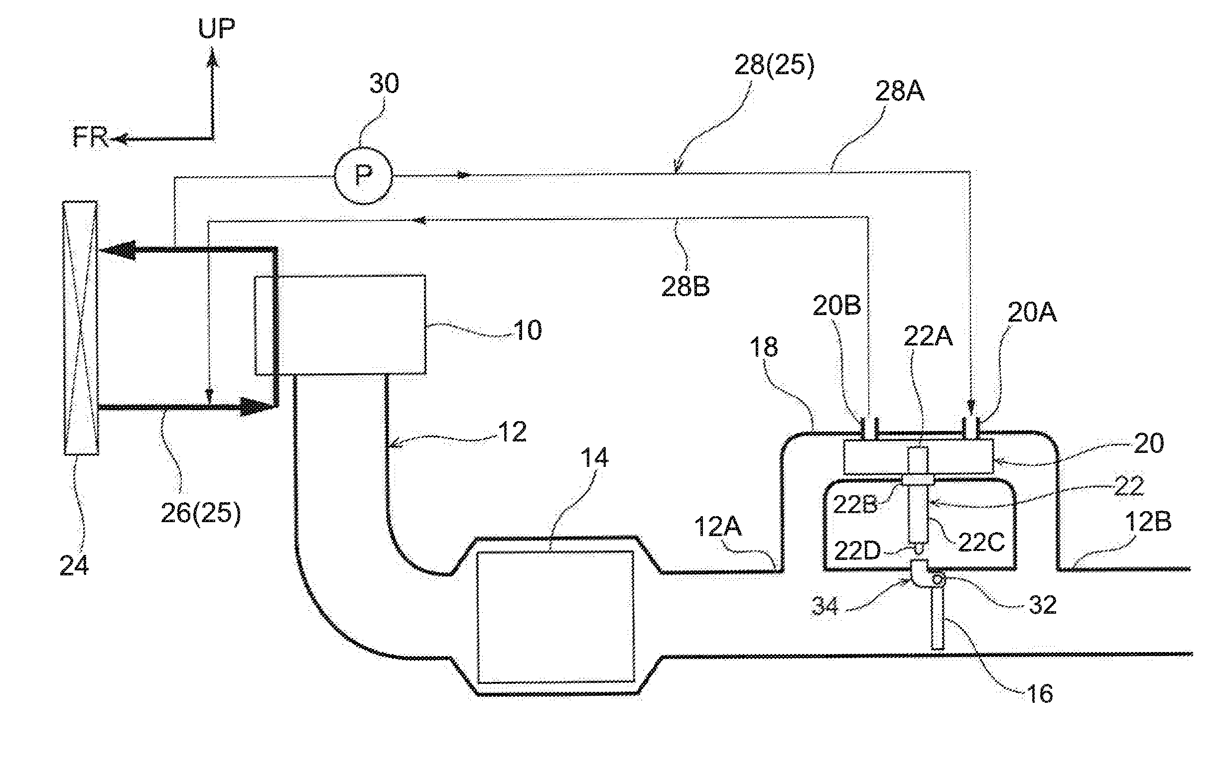
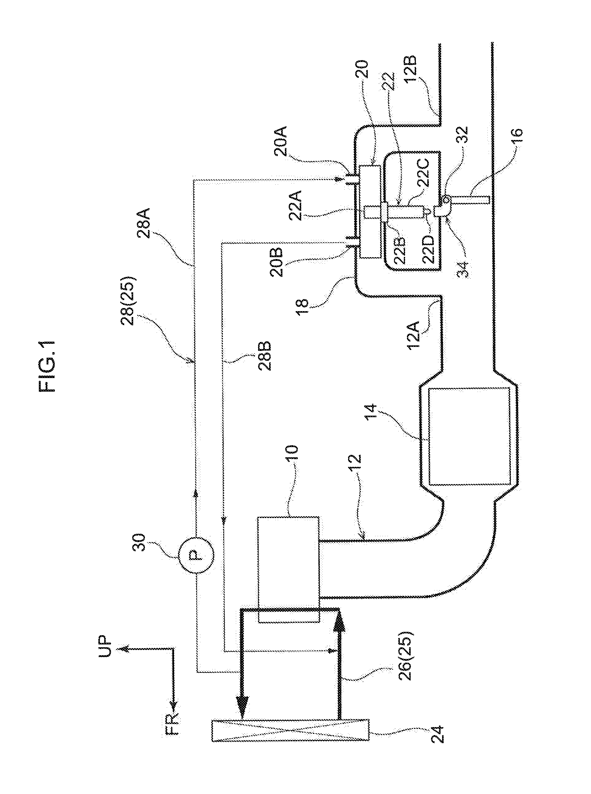
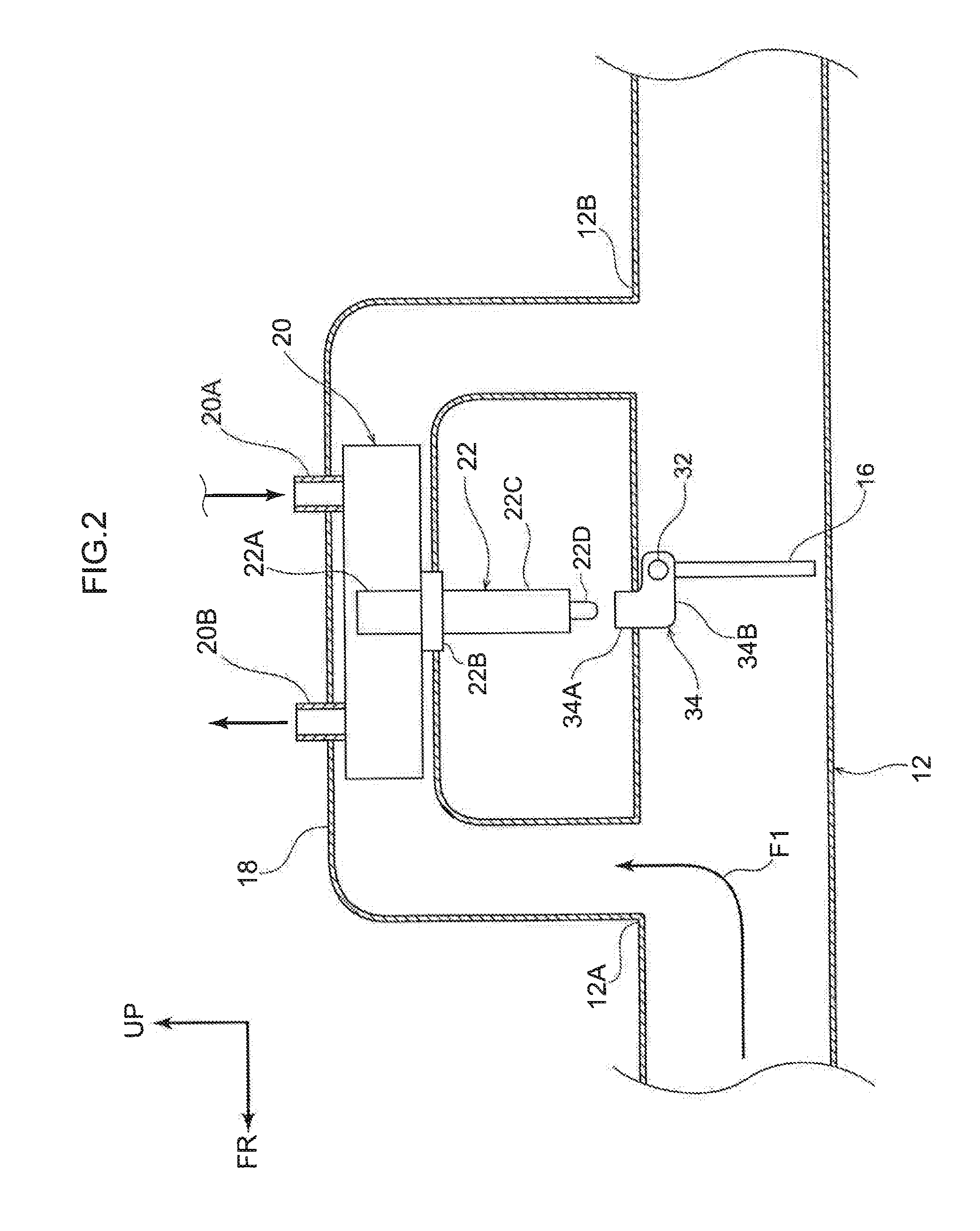
[0024]An exhaust heat recovery structure according to a first exemplary embodiment is described with reference to FIG. 1 to FIG. 3. The arrow FR that is shown as appropriate in the drawings indicates the vehicle front side of a vehicle in which the exhaust heat recovery structure is employed, the arrow UP indicates the vehicle upper side, and the arrow RH indicates the vehicle right side. In the following descriptions, where the directions front, rear, up, down, left and right are used without being particularly specified, the same represent the front and rear in the vehicle front-and-rear direction, up and down in the vehicle up-and-down direction, and left and right if facing in the running direction. For convenience of depiction, pipes are shown in section in the drawings.
[0025]As shown in FIG. 1, an exhaust system in which the exhaust heat recovery structure according to the present exemplary embodiment is employed has a structure in which a first pipe 12 is connected to an engi...
second exemplary embodiment
[0058]Now, an exhaust heat recovery structure according to a second exemplary embodiment is described with reference to FIG. 4 to FIG. 6. Overall structure of the exhaust system is similar to the structure in FIG. 2, apart from the principal portions shown in FIG. 4 to FIG. 6. Structures that are the same as in the first exemplary embodiment are assigned the same reference numerals and, as appropriate, are not described. For convenience of explanation, a driving cam 56 and the thermostat 22 are shown in FIG. 4 and FIG. 5. In practice, however, the driving cam 56 and the thermostat 22 would be disposed to the paper surface side of the drawing relative to a first pipe 52.
[0059]As shown in FIG. 4, the exhaust heat recovery structure according to the present exemplary embodiment is a coaxial-type structure in which the first pipe 52 and a second pipe 54 are provided concentrically. The first pipe 52 extends in the vehicle front-and-rear direction. Exhaust gas from the engine flows in th...
PUM
 Abstract
Description
Claims
Application Information