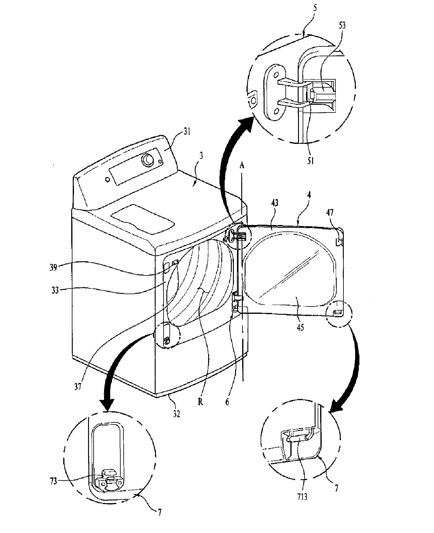
Laundry treating apparatus

Active Publication Date: 2017-01-12
LG ELECTRONICS INC
View PDF2 Cites 5 Cited by
  • Summary
  • Abstract
  • Description
  • Claims
  • Application Information

AI Technical Summary

Benefits of technology

The present invention provides a door handle system that allows for easy and smooth opening and closing of the door. It reduces the risk of injury to the user's nails and ensures stable rotation of the door without changing the rotational shaft. Additionally, it allows for the actuator to be pressed using the entire area of the user's middle knuckle, resulting in a smaller force requirement to rotate the door.

Problems solved by technology

In this case, a force for pressing the pressing point of the actuator should be focused on the end knuckle or fingertip, and there may be a risk that nails may be broken in case of a woman user.
In other words, a problem occurs in that the user should apply a force to the door in two directions (that is, direction for pressing the pressing point of the actuator and direction for pulling the door toward the body of the user) to rotate the door along a vertical direction.

Method used


Image

  • Laundry treating apparatus
  • Laundry treating apparatus
  • Laundry treating apparatus

Examples


first embodiment

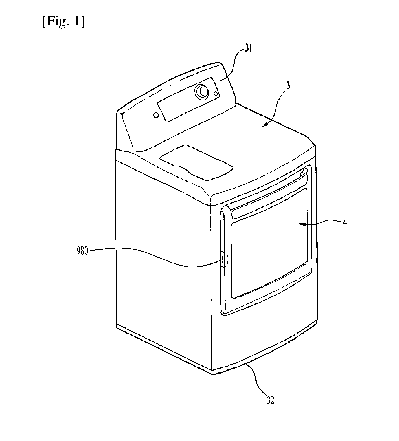
[0114]FIG. 7 is a diagram illustrating a structure of an actuator 990 according to the present invention. Motion of the first switching member 1000 according to actuation of the actuator 990 will be described in detail with reference to FIGS. 6 and 7.

[0115]First of all, the actuator 990 includes a pivot shaft 995 for pivoting the actuator 990, a first portion 996 extended from above the pivot shaft 995 beyond the povot shaft 995 toward the bottom 993 of the recessed part 992, and a second portion 997 extended from the end portion of the first portion 996 toward a space below the bottom 993 of the recessed part 992. At this time, the first portion 996 and the second portion 997 may be formed in a single body.

[0116]Also, the first portion 996 of the actuator 990 is provided with a pressing point 998 pressed by the user, wherein the pressing point 998 is arranged to be higher than the pivot shaft 995. In this case, the terminology “ressing point represents a portion of the actuator 990...

second embodiment

[0128]FIG. 8 is a diagram illustrating a structure of an actuator 990 according to the present invention. Motion of the first switching member 1000 according to pressurization of the actuator 990 will be described in detail with reference to FIGS. 6 and 8. Also, to assist understanding, the same reference numbers will be used throughout the drawings to refer to the same or like parts described in the embodiment of FIG. 7.

[0129]As described in the embodiment of FIG. 7, the actuator 990 according to this embodiment also includes a pivot shaft 995 for pivoting the actuator 990, a first portion 996 extended from the pivot shaft 995 toward the bottom 993 of the recessed part 992, and a second portion 997 extended from the end portion of the first portion 996 toward a space below the bottom 993 of the recessed part 992. At this time, the first portion 996 and the second portion 997 may be formed in a single body.

[0130]Also, the first portion 996 of the actuator 990 may be provided with a ...

third embodiment

[0157]FIG. 10 is a diagram illustrating a structure of an actuator 990 according to the present invention, and (a) and (b) of FIG. 11 are diagrams illustrating operation methods of the actuator shown in FIG. 10.

[0158]Hereinafter, a structure of the actuator according to the third embodiment of the present invention will be described with reference to FIG. 10 and (a) and (b) of FIG. 11.

[0159]A pivot shaft 995 of the actuator 990 according to this embodiment (FIG. 10, and (a) and (b) of FIG. 11) is located to be lower than the pressing point 998. That is, in this embodiment, the pivot shaft 995 of the actuator 990 may be provided between the first portion 996 and the second portion 997 of the actuator 990.

[0160]For example, the pivot shaft 995 may be located near the bottom 993 of the recessed part 992, and the pressing point 998 may be spaced apart upwardly from the bottom 993 of the recessed part 992 and thus may be located at the upper side of the recessed part 992. Meanwhile, the ...


PUM


Abstract

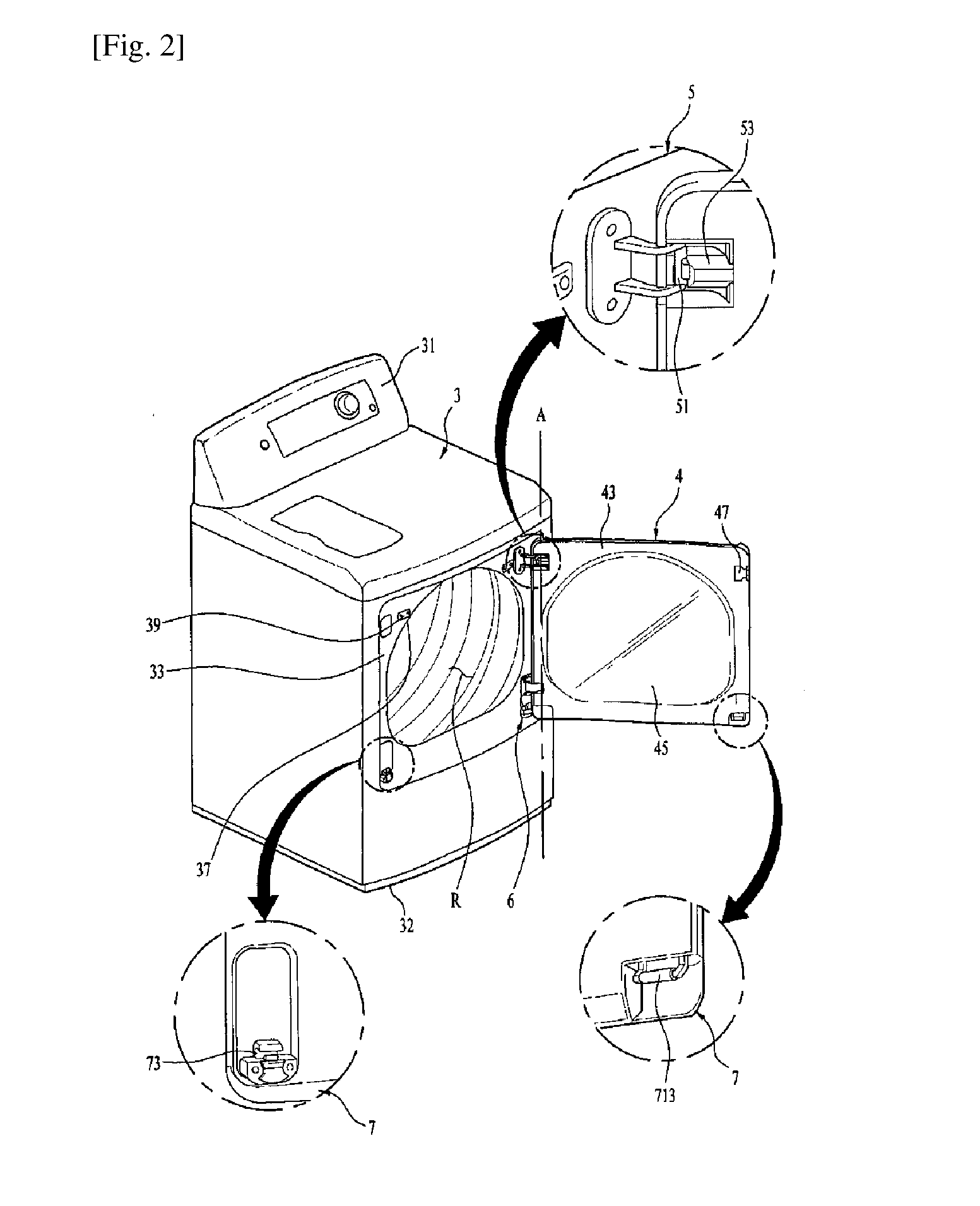
A laundry treating apparatus comprises a cabinet forming a profile, provided with a laundry opening; a door having an inner frame arranged toward the laundry opening and an outer frame coupled to the inner frame and arranged toward the outside of the cabinet, and opening and closing the laundry opening; a hinge part having a first pivot rotating the door along a first rotational direction and a second pivot rotating the door along a second rotational direction different from the first rotational direction; a pivot switching member movable to rotatably fix the door to any one of the first pivot and the second pivot; and a pressing piece provided in the door and pressed by a user to move the pivot switching member, wherein the pressing piece includes a pressing point pressed by the user, and the pressing point is provided at an upper end of the pressing piece.

Description

TECHNICAL FIELD[0001]The present invention relates to a laundry treating apparatus, and more particularly, to a laundry treating apparatus in which a door for opening and closing a laundry opening for loading of laundry may be opened rotatably in various directions.BACKGROUND ART[0002]A laundry treating apparatus may be categorized into a washing-only apparatus only having a washing function, a drying-only apparatus only having a drying function and a laundry washing / drying apparatus having both of the washing and drying functions. Each of the washing-only apparatus and the laundry washing / drying apparatus may include a tub provided in a cabinet and a drum rotatably provided in the tub, and the drying-only apparatus may include a drum rotatably provided in a cabinet.[0003]In a conventional laundry treating apparatus, a laundry opening for loading of the laundry is formed at the front of a body of the laundry treating apparatus, and a door may be installed to open and close the laund...

Claims


Application Information

Patent Timeline
IPC IPC(8): D06F39/14D06F58/20
CPCD06F58/20D06F39/14D06F37/28D06F37/42
Inventor LEE, CHANGHEONKIM, JAESEOKKANG, INCHEOLPARK, SOOWONLEE, HYUNTAEHWANG, INHOLEE, HYEOKJONGKIM, KIHYUK
Owner LG ELECTRONICS INC
Why Eureka
Try Eureka