Panel antenna

A flat-panel antenna and antenna technology, applied in the direction of the radiating element structure, the radiation unit cover, etc., can solve the problems of reduced transmission performance, deformation of the flat-panel antenna, short service life, etc., and achieve long transmission distance, light force, and small wind resistance. Effect

Inactive Publication Date: 2016-09-07
STATE GRID CORP OF CHINA +2
View PDF6 Cites 0 Cited by
  • Summary
  • Abstract
  • Description
  • Claims
  • Application Information

AI Technical Summary

Problems solved by technology

[0003] The purpose of the present invention is to provide a flat panel antenna, which is used to solve the problem that the flat panel antenna is prone to deformation during use under the condition of strong electromagnetic field interference and compact installation space, such as overhead lines of high-voltage transmission lines, and transmission Performance degradation, unstable signal, short service life and other technical problems

Method used


Image

  • Panel antenna
  • Panel antenna
  • Panel antenna

Examples


Embodiment Construction

[0020] It should be noted that, in the case of no conflict, the embodiments in the present application and the features in the embodiments can be combined with each other. The present invention will be described in detail below with reference to the accompanying drawings and embodiments.

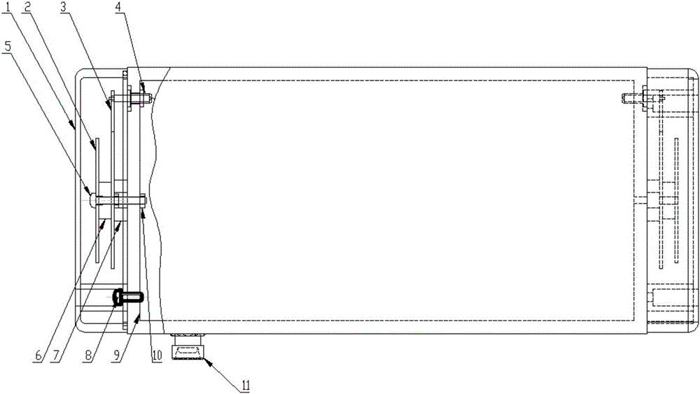
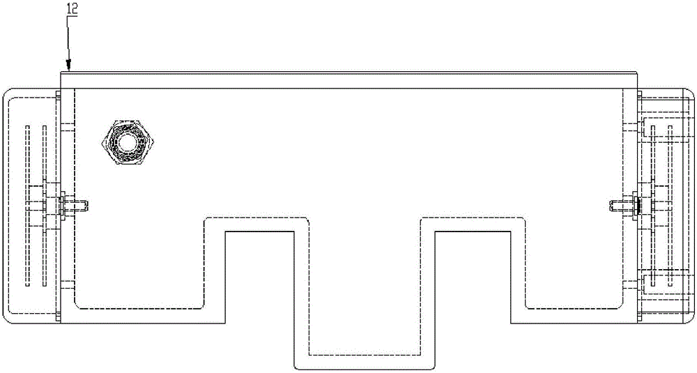
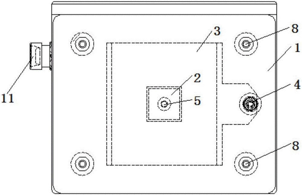
[0021] In order to solve technical problems such as strong electromagnetic field interference and compact installation space, such as overhead lines of high-voltage transmission lines, flat-panel antennas are prone to deformation during use, transmission performance declines, signal instability and short service life. , the present invention provides a flat panel antenna.

[0022] The panel antenna includes a housing as an antenna reflector, a radiation plate as an antenna emitter, and a small radiation plate. The small radiation plate is arranged at the front end of the radiation plate and is fixed on the housing by screws. A detection device is provided in the casing, and a connection ter...


PUM


Abstract

The invention discloses a panel antenna. The panel antenna comprises a housing serving as an antenna reflection plate as well as an emission plate and a small emission plate which serve as emitters of the antenna, wherein the small emission plate is arranged at the front end of the emission plate and is fixed to the housing through a screw; a detection apparatus is arranged in the housing; and a wiring terminal is arranged at one end of the emission plate and is connected with the detection apparatus through a signal line. Compared with a general panel antenna with the same area, the panel antenna has the advantages that in a signal set of the panel antenna, a signal transmission distance is farther, and the antenna deforms slightly during use, so that signals are stable.

Description

technical field [0001] The invention relates to the technical field of antennas for wireless communication products, in particular to a flat panel antenna used in a strong electromagnetic field environment. Background technique [0002] The existing common panel antenna adopts the structure of PCB printed antenna and reflector, which is easily disturbed under the condition of strong electromagnetic field. During outdoor use, the circuit board and the like are easily deformed, thereby reducing the transmission performance of the antenna, which is not suitable for long-distance signal transmission and has a short service life. Contents of the invention [0003] The purpose of the present invention is to provide a flat panel antenna, which is used to solve the problem that the flat panel antenna is prone to deformation during use under the condition of strong electromagnetic field interference and compact installation space, such as overhead lines of high-voltage transmission...

Claims


Application Information

Patent Timeline
Patent Type & Authority Applications(China)
IPC IPC(8): H01Q1/38H01Q1/42
CPCH01Q1/38H01Q1/42
Inventor 张景超王峥宋宁希梅林常刘娜陶留海李万胜夏传鲲秦福祥陈强李建平付文竹申换玲李鑫路
Owner STATE GRID CORP OF CHINA
Why Eureka
Try Eureka