
Method for monitoring a combustor

Inactive Publication Date: 2017-01-12
SIEMENS AG
View PDF3 Cites 1 Cited by
  • Summary
  • Abstract
  • Description
  • Claims
  • Application Information

AI Technical Summary

Benefits of technology

The patent describes a method to easily detect the formation of deposits in a combustor by measuring the distance between two fixed parts and evaluating any changes in that distance over time. This approach allows for cost-effective monitoring of potential deposit formation. The speed at which the distance variation occurs is measured and attributed to one of three monitoring objectives, which can help to better understand the behavior of the combustor and prevent damage from deposit formation. The method uses a single sensor to measure all three objectives simultaneously, making it more efficient and accurate than other methods.

Problems solved by technology

If a (low-quality) gaseous fuel, which does not conform to specific standards, is supplied to the combustor, contamination of internal cavities can occur.
The two main quality issues for gaseous fuels are liquid being carried over with the gas and high sulphur content in the gas.
The former can lead to burnout of components, whilst the latter can lead to blockage of passages of the combustor.
Both may lead to the combustor and thus the gas turbine engine to shut down.
As with gaseous fuel, liquid fuel quality varies from site to site, whereas a poor quality of the fuel has a negative impact upon the operation of the gas turbine engine, because carbon can build up on key components blocking holes.
This may lead to a restriction of the fuel flow.
Or fixed maintenance intervals may be too long.
This may lead to a damaging of the combustor and thus to an unscheduled downtime of the combustor and the gas turbine engine.

Method used


Image

  • Method for monitoring a combustor
  • Method for monitoring a combustor
  • Method for monitoring a combustor

Examples


Embodiment Construction

[0030]The terms upstream and downstream refer to the flow direction of the airflow and / or working gas flow through the engine unless otherwise stated. The terms forward and rearward refer to the general flow of gas through the engine. The terms axial, radial and circumferential are made with reference to a rotational axis 20 of the gas turbine engine.

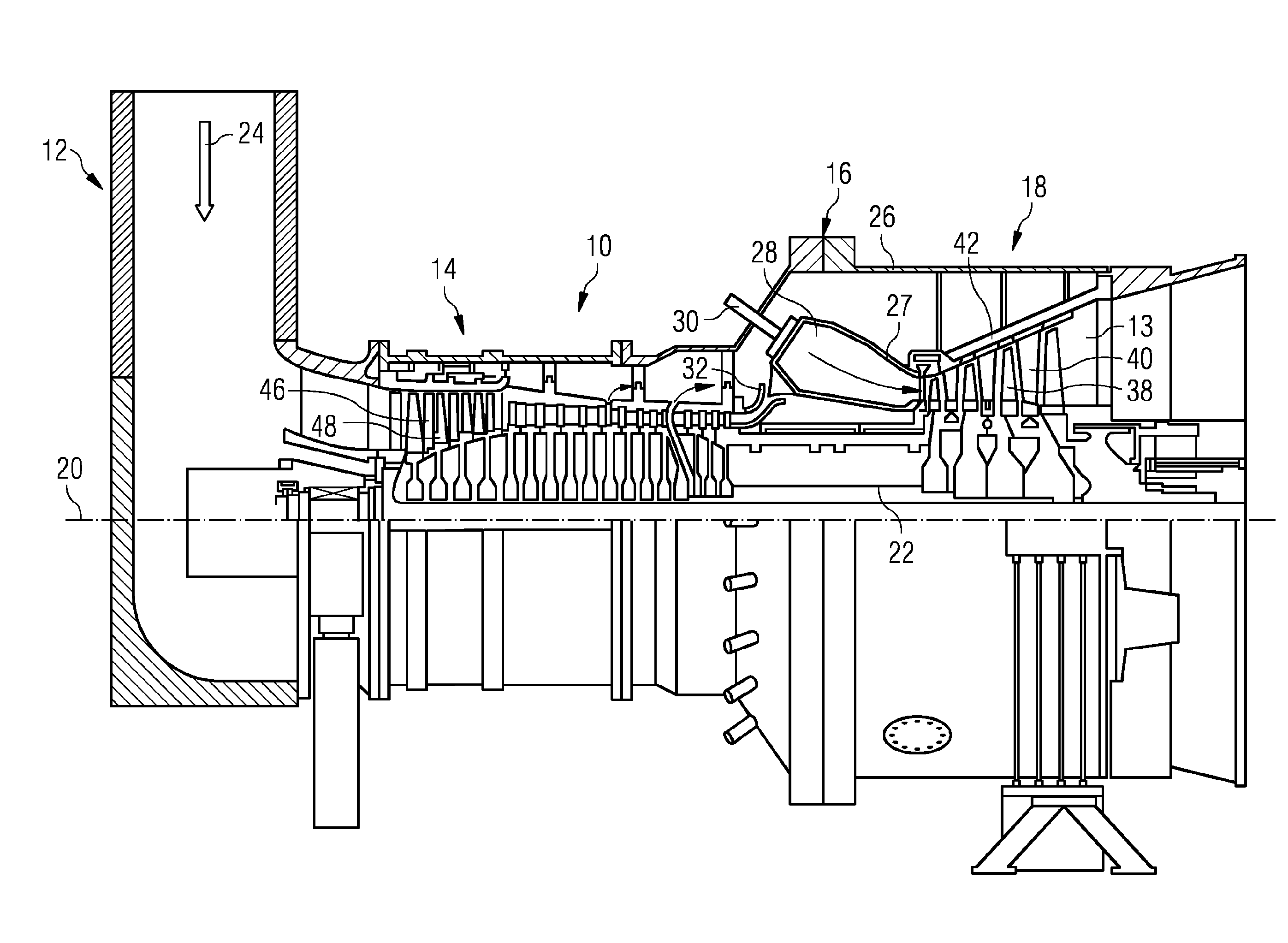
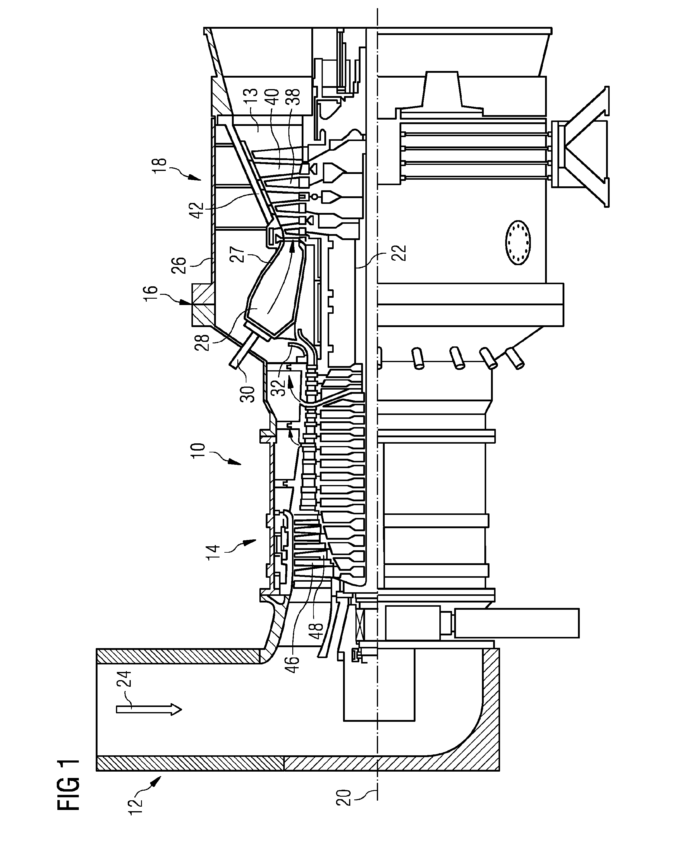
[0031]FIG. 1 shows an example of a gas turbine engine 10 according to the invention in a sectional view. The gas turbine engine 10 comprises, in flow series, an air inlet 12, a compressor section 14, a combustor section 16 and a turbine section 18 which are generally arranged in flow series and generally in the direction of the rotational axis 20 (which is thus also the longitudinal axis of the gas turbine engine 10). The gas turbine engine 10 further comprises a shaft 22 which is rotatable about the rotational axis 20 and which extends longitudinally through the gas turbine engine 10. The shaft 22 drivingly connects the turbine section...


PUM


Abstract

A method for monitoring a combustor comprising: measuring several times a distance between a first wall of the combustor and either a second wall of the combustor or a sensor of the combustor by the sensor, and concluding from a variation in the distances a formation of deposit on the first and / or second wall and / or sensor, and / or a temperature change within the combustor, and / or a pressure change within the combustor.

Description

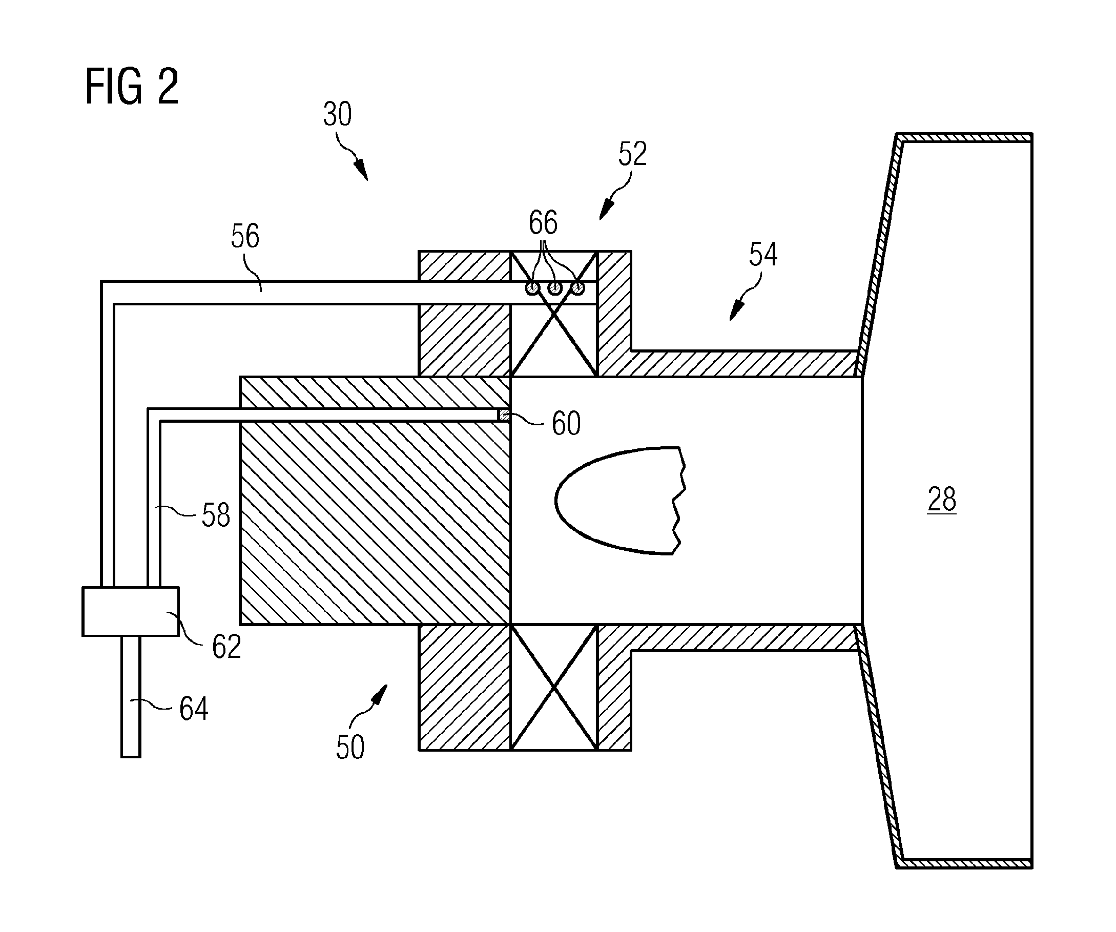
CROSS REFERENCE TO RELATED APPLICATIONS[0001]This application is the US National Stage of International Application No. PCT / EP2015 / 050102 filed Jan. 6, 2015, and claims the benefit thereof. The International Application claims the benefit of European Application No. EP14153834 filed Feb. 4, 2014. All of the applications are incorporated by reference herein in their entirety.FIELD OF INVENTION[0002]The present invention is directed to a method for monitoring a combustor and to a combustor being adapted to be monitored by said method. The combustor may be part of a gas turbine engine.BACKGROUND OF INVENTION[0003]A typical gas turbine engine comprises an air inlet followed by a compressor section in which incoming air is compressed. Afterwards, the compressed air is guided to one or more combustors in a combustor section of the gas turbine engine. A fuel, which may be a gaseous or liquid fuel, is introduced into the combustors and mixed with a portion of the compressed air. Hot combust...

Claims


Application Information

Patent Timeline
IPC IPC(8): F01D21/10G01N29/04F02C7/30
CPCF01D21/10G01N29/04F02C7/30F23N5/16F23N5/242F23R3/00G01N29/07F23D2208/10F23D2900/00016F23R2900/00004G01N2291/0258G01N2291/044G01N2291/102
Inventor BULAT, GHENADIEHEADLAND, PAUL
Owner SIEMENS AG
Learn More