
Display device

a display device and display technology, applied in the direction of instruments, static indicating devices, etc., can solve the problem of difficulty in simply making the power supply device thinner, and achieve the effect of improving power supply efficiency, making thinner and lighter

Active Publication Date: 2017-01-12
JOLED INC
View PDF11 Cites 11 Cited by
  • Summary
  • Abstract
  • Description
  • Claims
  • Application Information

AI Technical Summary

Benefits of technology

The invention is a display device that is more efficient in its power supply and can be made thinner and lighter. This makes it easier to handle and use the device in a convenient way.

Problems solved by technology

The size of a power supply device, among the structures other than the organic EL display panel, depends on power consumption of the organic EL display panel, and therefore it is difficult to simply make the power supply device thinner.

Method used


Image

  • Display device
  • Display device
  • Display device

Examples


embodiment

[0035]Hereinafter, an embodiment will be described in detail with reference to the Drawings where necessary. Note, however, that detailed descriptions may be omitted where unnecessary. For example, detailed descriptions of well-known aspects or repetitive descriptions of essentially similar configurations may be omitted. This is to avoid redundancy and make the following description easier for those skilled in the art to understand.

[0036]Note that the inventor provides the accompanying Drawings and the following description not to limit the scope of the claims, but to aid those skilled in the art to adequately understand the present disclosure.

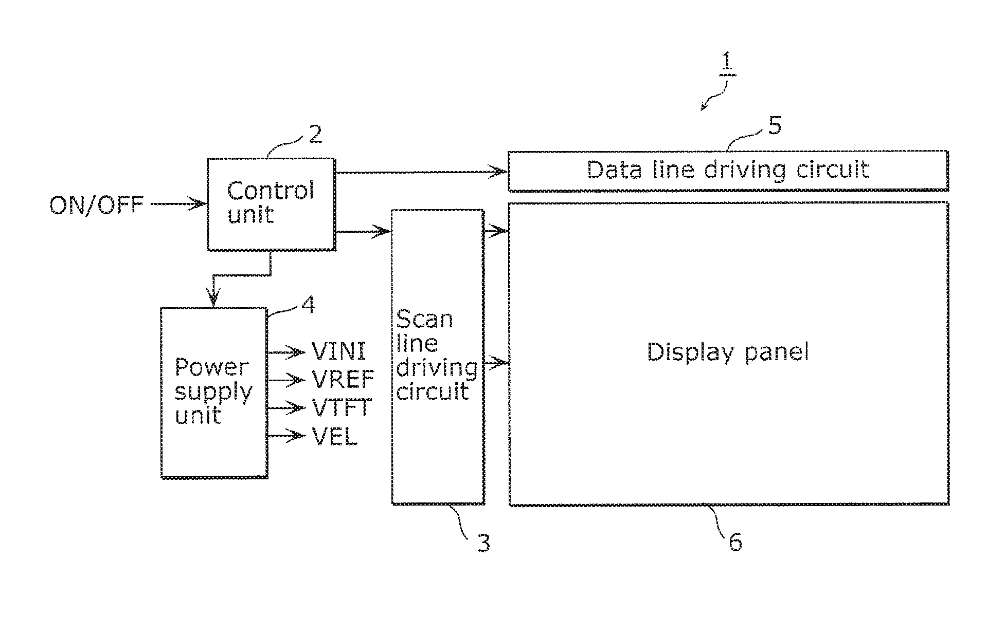
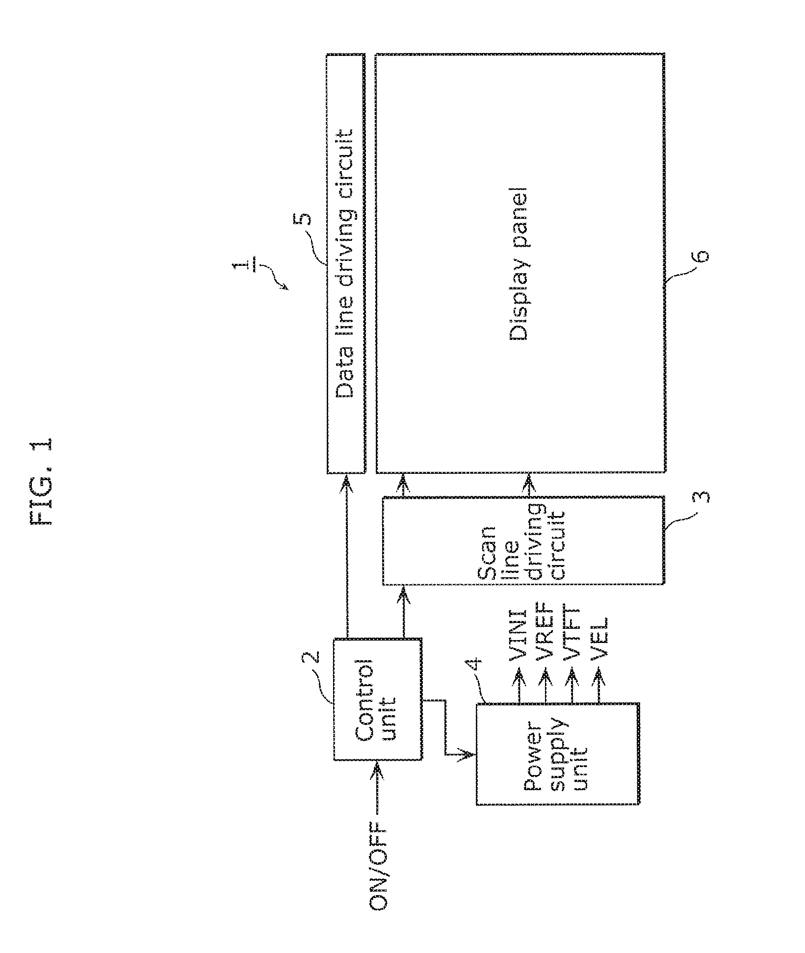
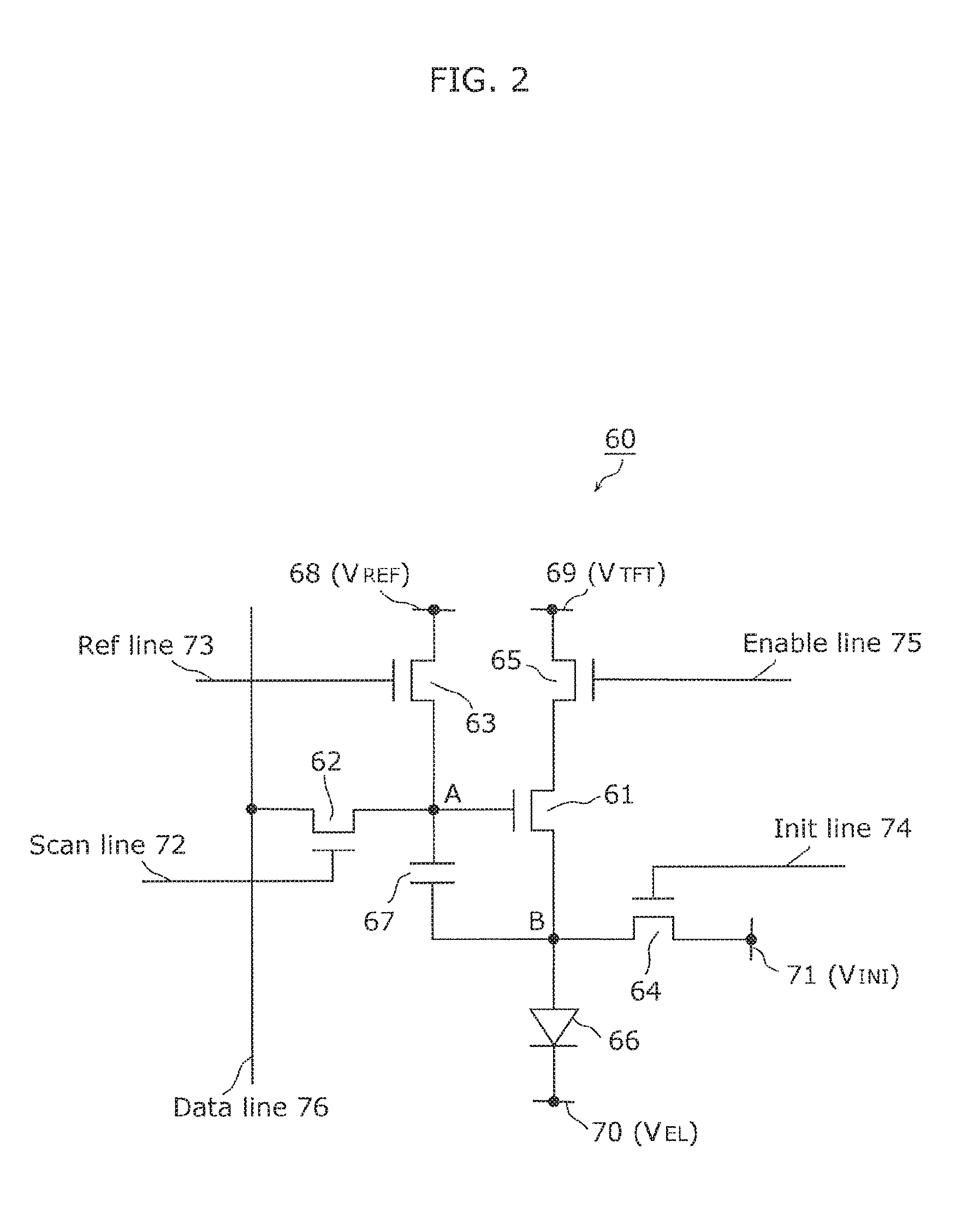
[0037]Hereinafter, a display device according to the embodiment will be described with reference to FIG. 1 to FIG. 4A and FIG. 4B.

[0038]1. Configuration of Display Device

[0039]FIG. 1 is a block diagram illustrating an example of a configuration of a display device according to an embodiment. FIG. 2 is a circuit diagram illustrating an example ...


PUM


Abstract

A display device in the present disclosure includes: a plurality of pixel circuits that are arranged in a matrix and supplied with power through a first power supply line maintained at a first voltage and a second power supply line maintained at a second voltage having a positive value less than the first voltage; a first power supply circuit of a synchronous rectification type that outputs the first voltage to the first power supply line by chopping an input voltage; and a second power supply circuit of the synchronous rectification type that outputs the second voltage to the second power supply line by chopping the first voltage.

Description

TECHNICAL FIELD[0001]The present disclosure relates to display devices, and particularly to a display device using a light-emitting element which emits light according to an electrical current.BACKGROUND ART[0002]A display device using an organic electroluminescent (EL) element is known as an example of a display device using a current-driven light-emitting element.[0003]An organic EL display device using a self-luminous organic EL element does not require a backlight, which a liquid-crystal display device requires, and therefore is most suitable when a thinner display device is desired. Since there is no limit on a viewing angle of the organic EL display device, the organic EL device is expected to be put to practical use as a next-generation display device. The organic EL element used in the organic EL display device is different from a liquid-crystal cell in that luminance of each light-emitting element is controlled by a value of a current flowing therethrough whereas the liquid...

Claims


Application Information

Patent Timeline
Patent Type & Authority Applications(United States)
IPC IPC(8): G09G3/3233G09G3/3283G09G3/3266
CPCG09G3/3233G09G3/3266G09G3/3283G09G2320/0646G09G2300/0866G09G2300/0809G09G2300/0842G09G3/2092G09G3/3696G09G2300/0814G09G2310/08G09G2330/028G09G3/3291G09G2300/0819G09G2300/0861
Inventor NAKATANI, TOSHIKUNI
Owner JOLED INC
Learn More