
Screenless panels for a grain dryer

Inactive Publication Date: 2017-01-26
SUKUP MFG
View PDF3 Cites 0 Cited by
  • Summary
  • Abstract
  • Description
  • Claims
  • Application Information

AI Technical Summary

Benefits of technology

The patent is about a new design for a grain dryer that uses screenless panels with cut outs to receive heated air from a heating system. These panels also have deflectors attached above the cut outs to prevent debris and grain fines from obstructing airflow. The deflectors have a connecting section and a deflecting section that is bent away from the connecting section along a bend line. These deflectors are connected to the panels by bolts placed through aligned apertures in the panels and deflectors. The technical effect of this design is that it allows for better heating of the grain and prevents clogging of the airflow paths, which results in more efficient and effective grain drying.

Problems solved by technology

While useful, the perforated panels tend to restrict air flow and can become covered and plugged with debris and grain fines.

Method used


Image

  • Screenless panels for a grain dryer
  • Screenless panels for a grain dryer
  • Screenless panels for a grain dryer

Examples


Embodiment Construction

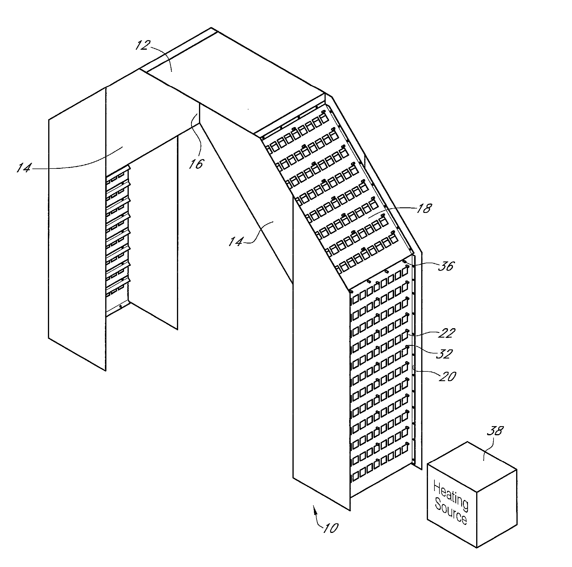
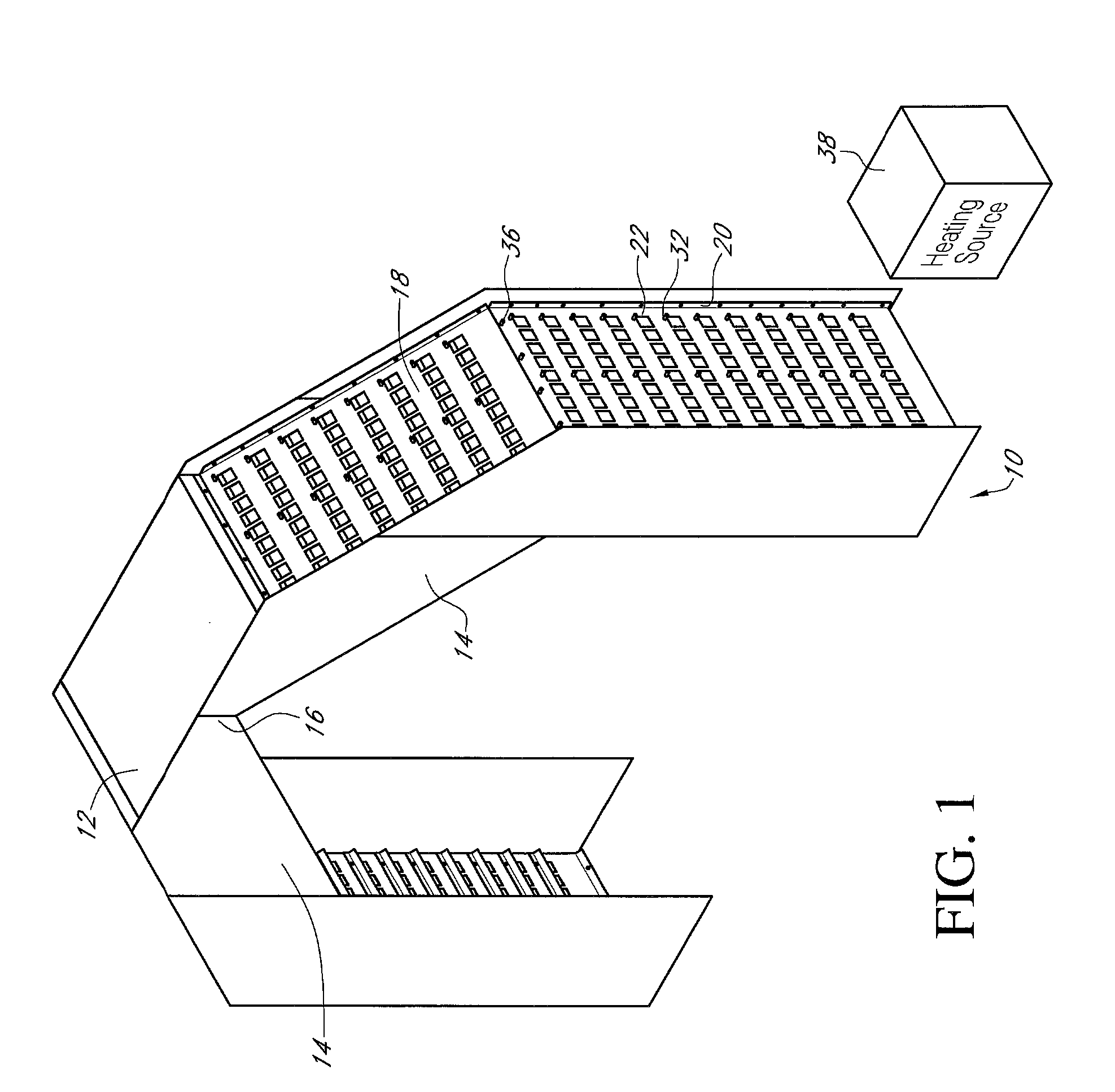
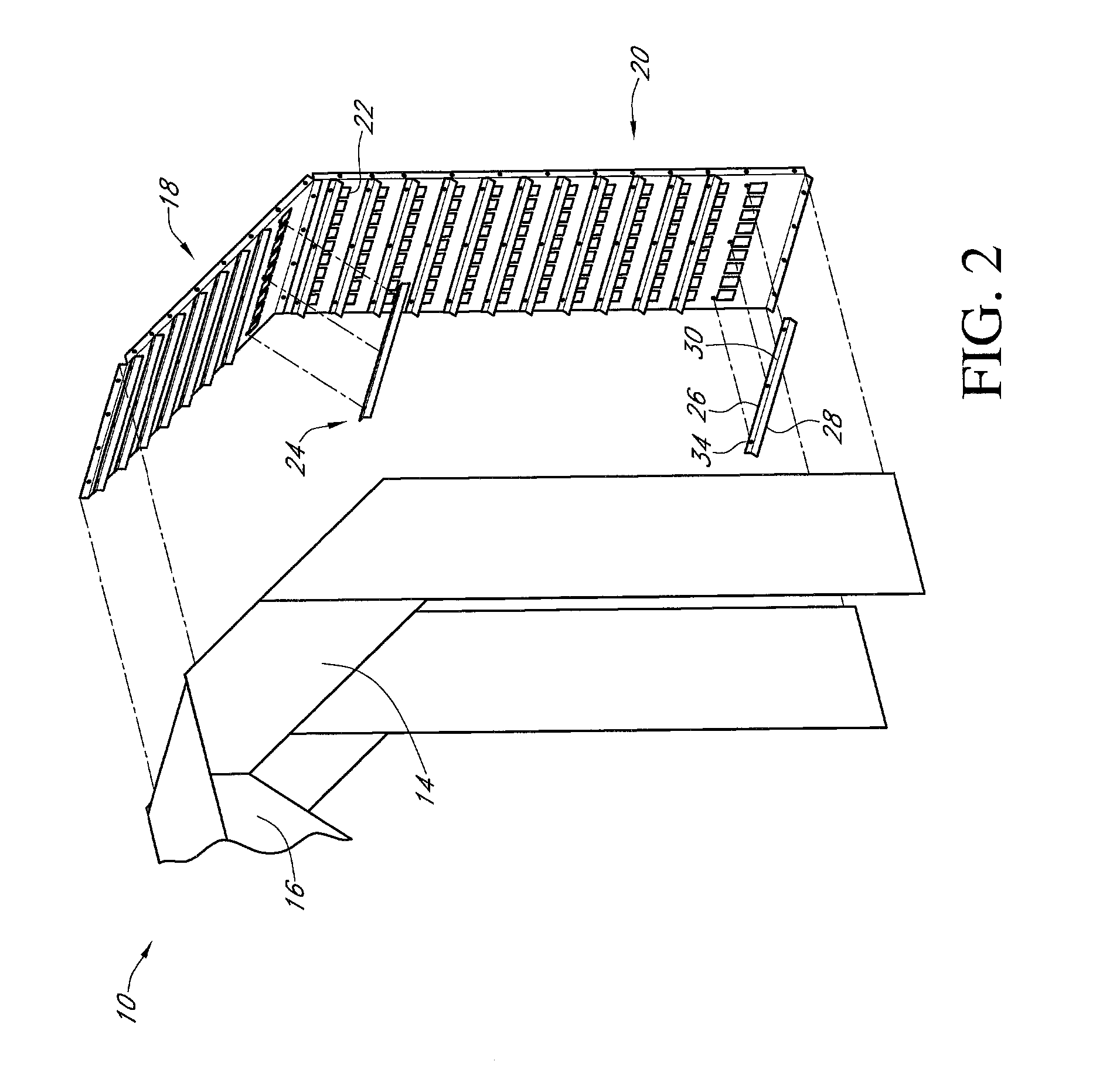
[0010]Referring to the Figures, a grain dryer 10 has a grain intake 12 that feeds grain into a pair of pathways 14 that form a central dryer chamber or plenum 16. The pathways 14 are formed, in part, by inner and outer panels 18 and 20. The panels 18 and 20 have a plurality of cutouts 22 that preferably are aligned and square, but can be positioned in any manner and in any size and shape.

[0011]Attached to panels 18 and 20 within the pathway 14 are a plurality of deflectors 24. The deflectors 24 are preferably elongated having a connecting section 26 and a deflecting section 28. The deflecting section 28 is bent in relation to the connecting section 26 along bend line 30. Preferably the deflecting section 28 is bent at a thirty degree angle in relation to the connecting section 26.

[0012]The connecting section 26 have a plurality of apertures 32 that align with apertures 34 in panels 18 and 20. Bolts 36 are received within apertures 32 and 34 to secure the deflectors 24 to the panels ...


PUM


Abstract

A plurality of screenless panels for a grain dryer having a plurality of cut outs to receive forced heated air from a heating system. The panels have a plurality of deflectors attached above the cut outs of the panels such that debris and grain fines is prevented from obstructing airflow. The deflectors have a connecting section and a deflecting section that is bent away from the connecting section along a bend line. The deflectors are connected to the panels by bolts placed through aligned apertures in the panels and deflectors.

Description

BACKGROUND OF THE INVENTION[0001]This invention is directed toward grain drying and more particularly to a screenless panel used with a cross flow dryer.[0002]Cross flow dryers are well known in the art. These dryers have grain pathways that are formed by perforated panels. Typically the perforations, that are approximately 0.094 inches in diameter, permit heated air to pass through the pathways to dry grain. While useful, the perforated panels tend to restrict air flow and can become covered and plugged with debris and grain fines. As a result, the dryers require cleaning in order to maintain dryer capacity and efficiency. Therefore, a need exists in the art for a device that addresses these deficiencies.[0003]An objective of the present invention is to provide a screenless panel for a grain dryer that reduces or eliminates plugging of debris and grain fines.[0004]A further objective of the present invention is to provide a screenless panel for a grain dryer where it is easier to m...

Claims


Application Information

Patent Timeline
IPC IPC(8): F26B17/12
CPCF26B17/122F26B17/126F26B25/12
Inventor BROWNMILLER, DAVID J.
Owner SUKUP MFG
Learn More