Co-molded sealing ring for use in an electrical fitting, and a raintight compression connector and raintight compression coupler incorporating a co-molded sealing ring

a technology for sealing rings and electrical fittings, which is applied in the direction of engine seals, sleeve/socket joints, pipe joints, etc., can solve the problems that existing connectors and couplers may have difficulty maintaining a raintight connection

Active Publication Date: 2017-02-02
BRIDGEPORT FITTINGS LLC
View PDF1 Cites 22 Cited by
  • Summary
  • Abstract
  • Description
  • Claims
  • Application Information

AI Technical Summary

Problems solved by technology

It has been observed that existing connectors and couplers may have difficulty maintaining a raintight connection due to sealing surface imperfections of the EMT or RMC outside diameters, especially with larger diameter trade sizes.

Method used


Image

  • Co-molded sealing ring for use in an electrical fitting, and a raintight compression connector and raintight compression coupler incorporating a co-molded sealing ring
  • Co-molded sealing ring for use in an electrical fitting, and a raintight compression connector and raintight compression coupler incorporating a co-molded sealing ring
  • Co-molded sealing ring for use in an electrical fitting, and a raintight compression connector and raintight compression coupler incorporating a co-molded sealing ring

Examples


Embodiment Construction

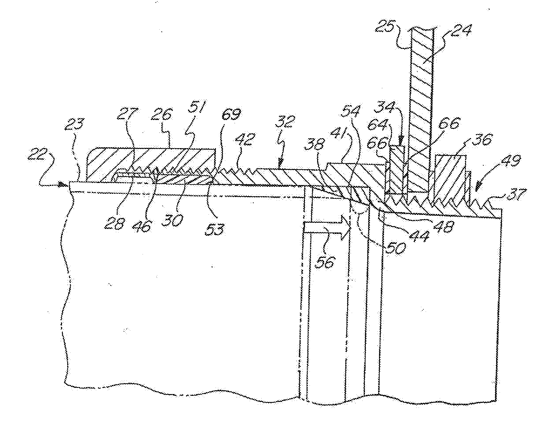
[0061]The present invention, as shown in FIGS. 21-28, is an improvement to what is called an upper sealing ring 30′ as discussed initially below with respect to FIGS. 1-20. This improvement is a co-molded sealing ring 30* and is described below following the discussion of FIGS. 1-20.

[0062]As discussed in applicant's co-pending U.S. application Ser. No. 15 / 079,148, the prior invention discussed therein is directed to an improved upper sealing ring 30′ forming part of a raintight compression connector 20 or a raintight compression coupler 20′ as discussed below.

[0063]PRIOR IMPROVED UPPER SEALING RING (FIGS. 1-20)

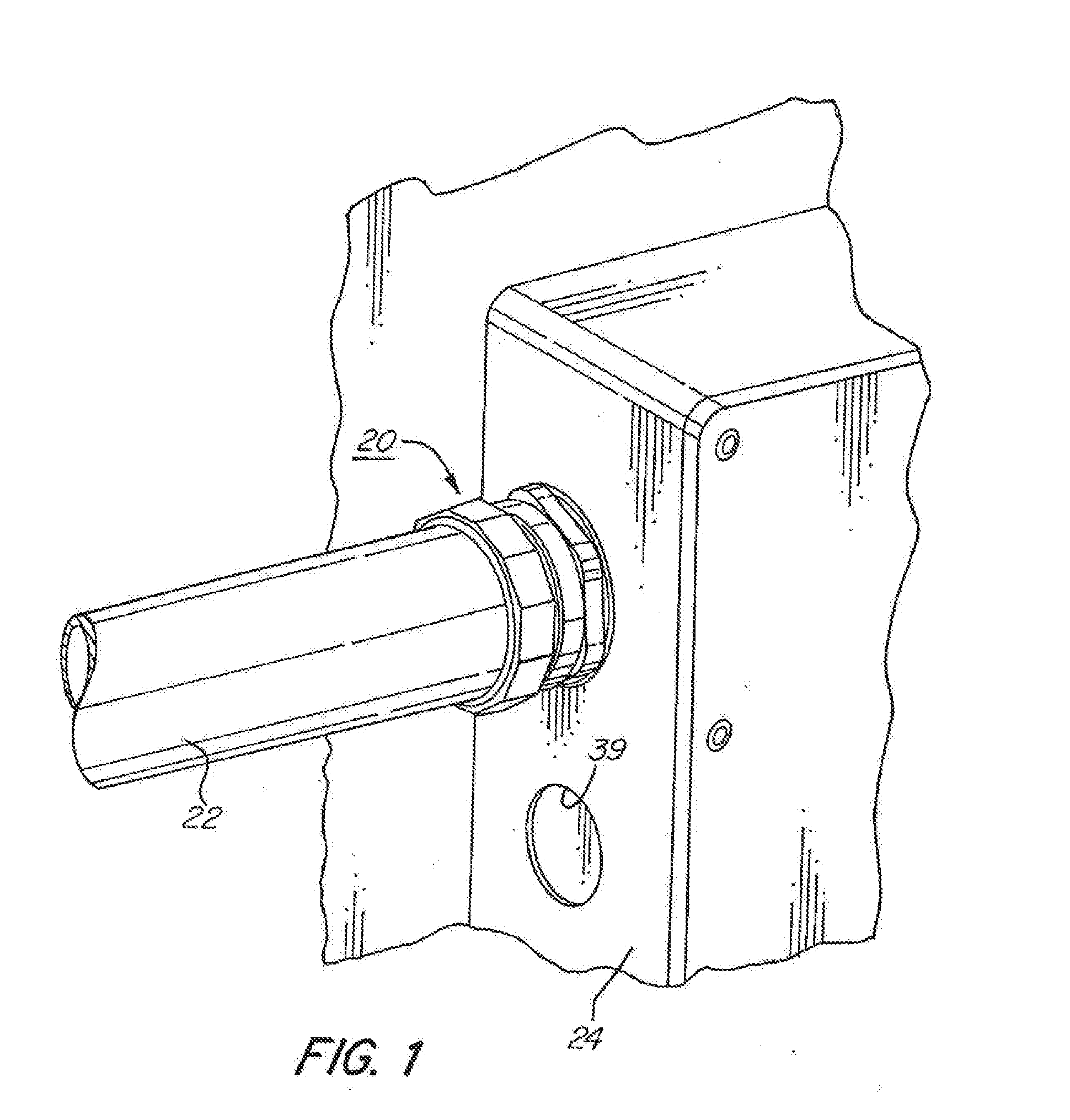
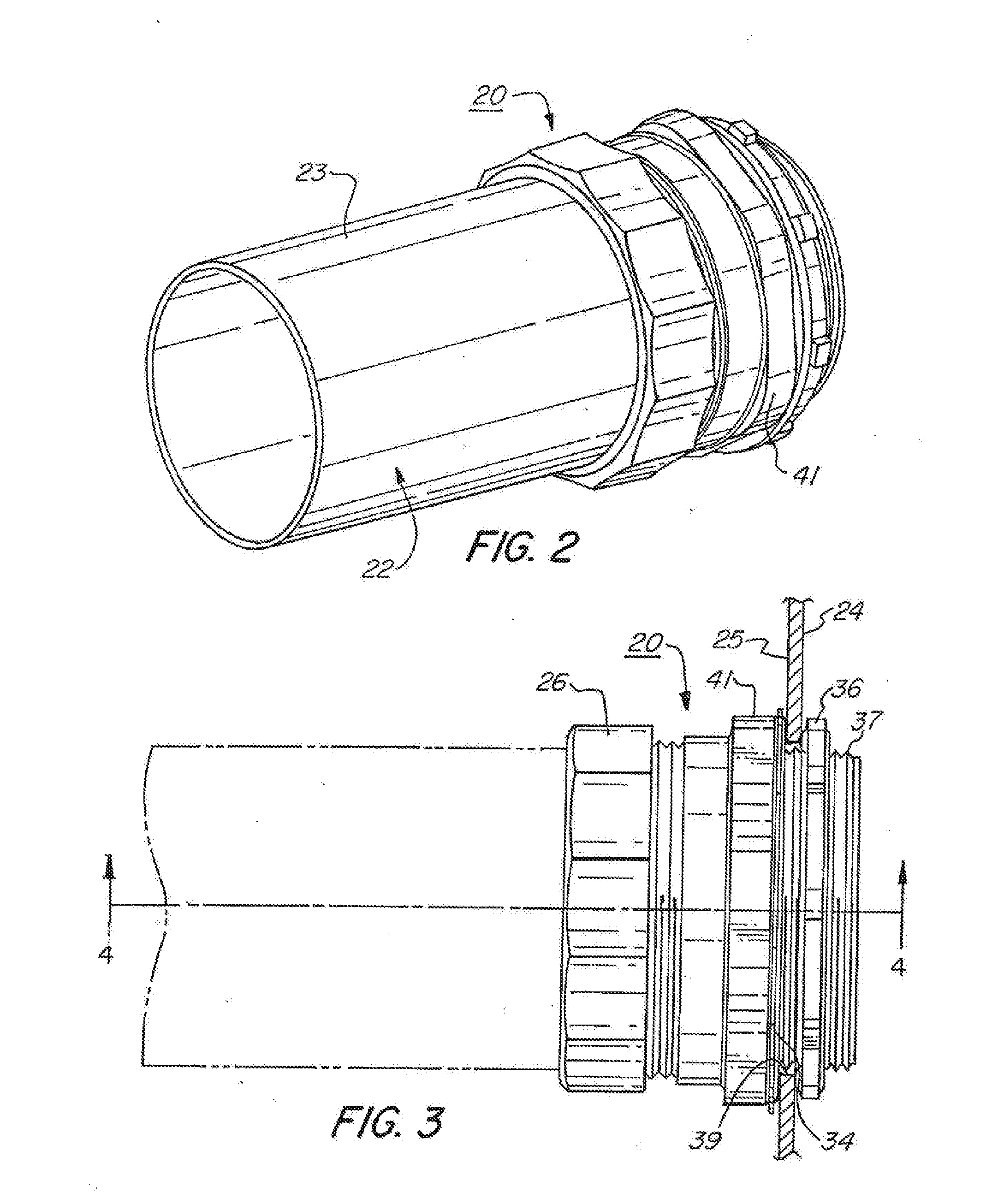
[0064]As seen in FIG. 1, an embodiment of a raintight compression connector 20 according to the prior invention is configured for receipt of an electrical metallic tubing or rigid metallic conduit (EMT or RMC) 22 (collectively referred to as conduit) so as to form a raintight seal between the EMT or RMC and an electrical enclosure 24 to which the compression connector is attac...


PUM


Abstract

A co-molded sealing ring for use in an electrical fitting has an uncompressed state and a compressed state and includes a first segment formed from thermoplastic elastomer and a second segment co-molded to the first segment, formed from a medium-density polyethylene material. A space formed between the first segment and an inner surface of an electrical fitting connector body when the ring is in the uncompressed state, is at least partially filled by a portion of the first segment when the ring is in the compressed state; the second segment having an end surface positioned away from the first segment, the end surface dimensioned for contact by a gland ring so as to urge the sealing ring into the compressed state so that the first segment forms a seal between the inner surface of the connector body and an outer surface of a conduit positioned within the connector body.

Description

CROSS REFERENCE TO RELATED APPLICATIONS[0001]This application claims priority to U.S. Utility patent application No. 15 / 079,148 filed on Mar. 24, 2016, which in turn claims priority to U.S. Utility patent application No. 14 / 068,663 filed on Oct. 31, 2013, which in turn claims priority to U.S. Provisional Patent Application No. 62 / 142,150 filed on Apr. 2, 2015. The contents of all of these applications are also hereby incorporated by reference in their entirety.FIELD OF THE INVENTION[0002]This invention is directed to a co-molded sealing ring for use in an electrical fitting, including a raintight compression connector for securing electrical metallic tubing (EMT), or rigid metallic conduit (RMC) to an electrical enclosure and to a raintight compression coupler for securing two EMT's or RMC's to each other. The invention is thus with respect to a co-molded sealing ring, taken alone or in combination with a raintight compression connector or a raintight compression coupler.BACKGROUND ...

Claims


Application Information

Patent Timeline
Patent Type & Authority Applications(United States)
IPC IPC(8): F16L5/08F16L21/04F16J15/02
CPCF16L5/08F16L21/04F16J15/022H02G3/0616
Inventor DECESARE, CHRISTOPHER W.SMITH, LAWRENCE J.
Owner BRIDGEPORT FITTINGS LLC
Why Eureka
Try Eureka