

Grow light matrix system using spacers to maintain proper light position
- Summary
- Abstract
- Description
- Claims
- Application Information
AI Technical Summary
Benefits of technology
Problems solved by technology
Method used
Image

Examples
Embodiment Construction
[0010]This Summary is provided to introduce a selection of concepts in a simplified form that are further described below in the Detailed Description. This Summary is not intended to identify key features or essential characteristics of the claimed subject matter, nor is it intended to be used as an aid in determining the scope of the claimed subject matter.
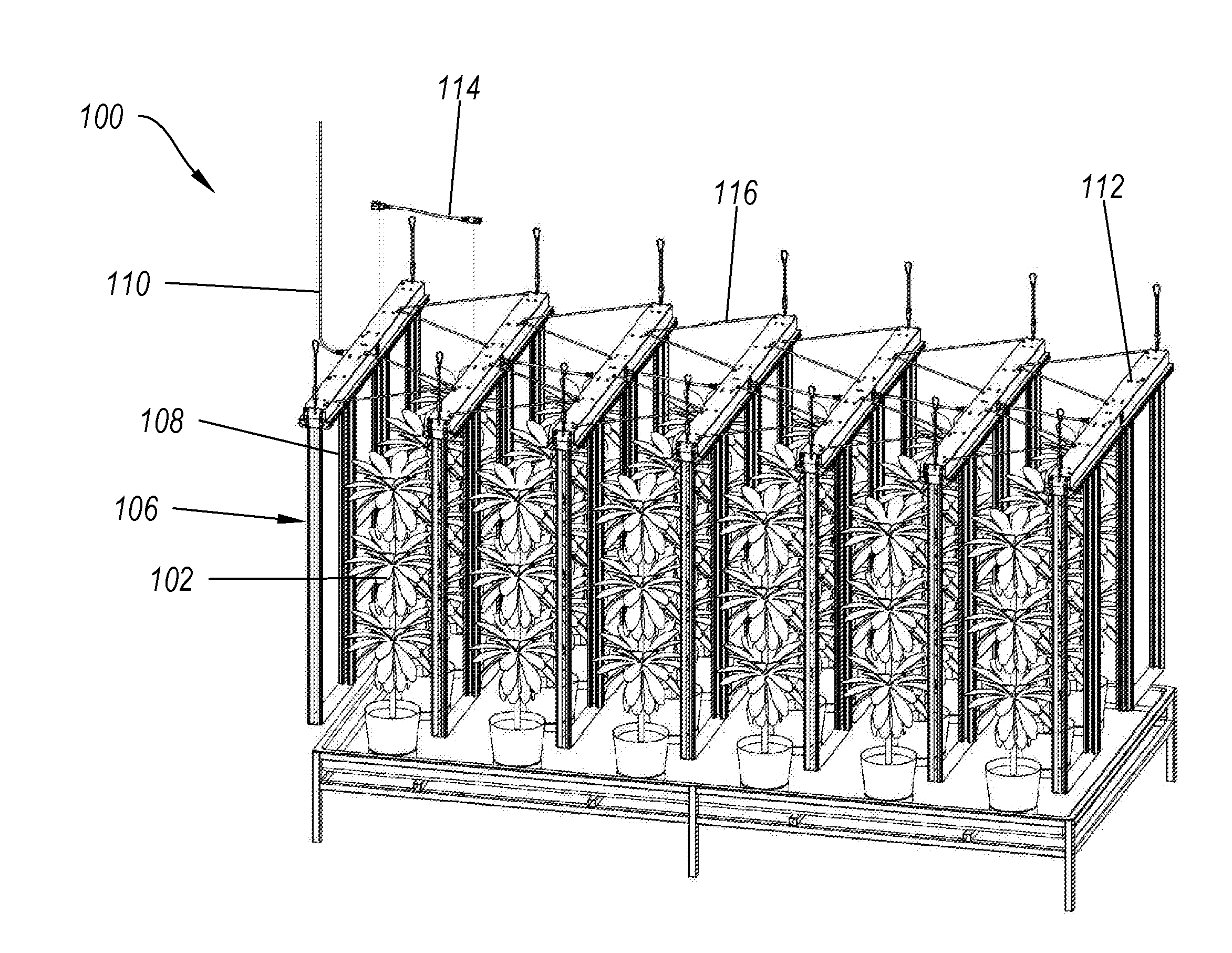
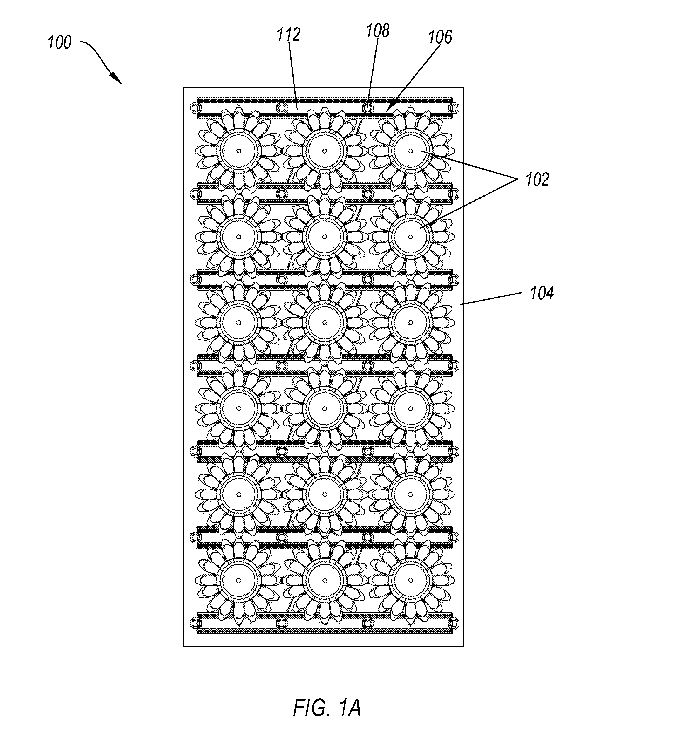
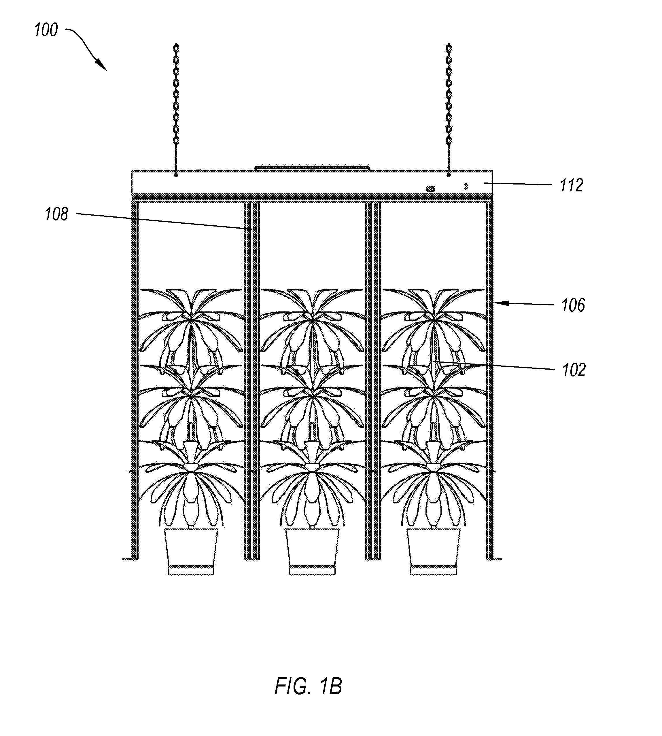
[0011]One example embodiment includes a lighting system for stimulating plant growth. The system includes three or more plants in a grow area, wherein the centers of least three of the three or more plants are not substantially coincident to a line located on any plane. The system also includes a first array of light fixtures and a second array of light fixtures. The light fixtures in the first array of light fixtures and second array of light fixtures are positioned vertically such that at least a portion of each of the light fixtures is below the top of the three or more plants and are located such that each plant is exposed to...
PUM
 Abstract
Description
Claims
Application Information