Liquid Crystal Panel Fixing Assembly And Display Device

a technology of fixing assembly and liquid crystal panel, applied in non-linear optics, instruments, optics, etc., can solve the problem that the conventional fixing method cannot meet the above requirements, and achieve the effect of increasing compatibility of backlight modules and reducing the cost of developing different backlight modules for different liquid crystal panels

Active Publication Date: 2017-02-02
SHENZHEN CHINA STAR OPTOELECTRONICS TECH CO LTD
View PDF2 Cites 1 Cited by
  • Summary
  • Abstract
  • Description
  • Claims
  • Application Information

AI Technical Summary

Benefits of technology

[0016]In the present invention, through designing a liquid crystal panel fixing assembly and using the frame structure to support the liquid crystal panel. At each edge of the frame structure. A location adjustable position-limiting block is provided. Through changing the location of the position-limiting block at each edge of the frame structure, fixing liquid crystal panels having different sizes is convenient to achieve. The cost for developing different backlight modules for different liquid crystal panels is reduced, and the compatibility of a backlight module is increased.

Problems solved by technology

However, the conventional fixing method cannot satisfy the above requirement.

Method used


Image

  • Liquid Crystal Panel Fixing Assembly And Display Device
  • Liquid Crystal Panel Fixing Assembly And Display Device
  • Liquid Crystal Panel Fixing Assembly And Display Device

Examples


embodiment 1

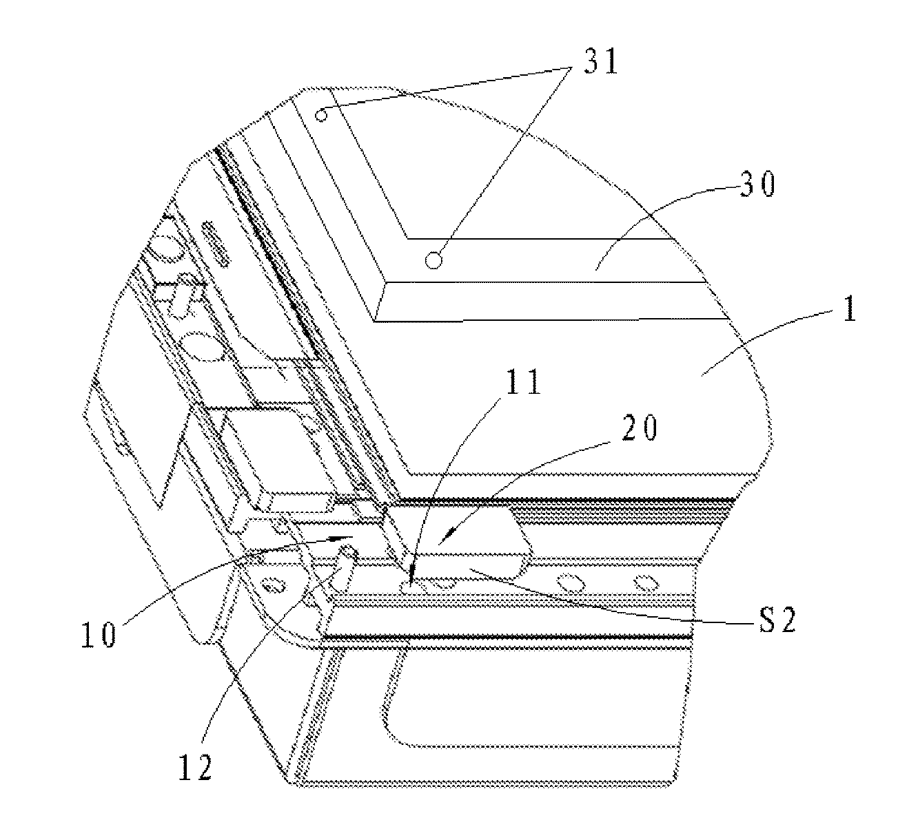
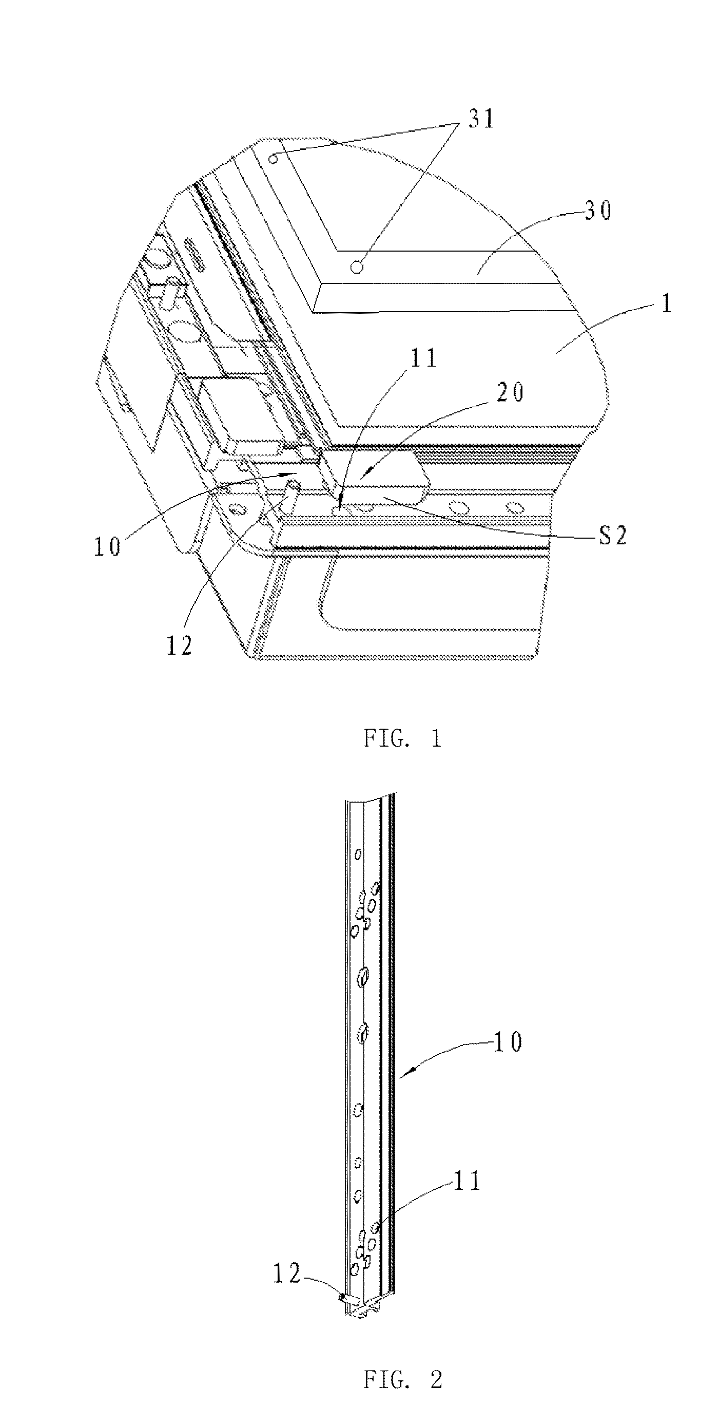
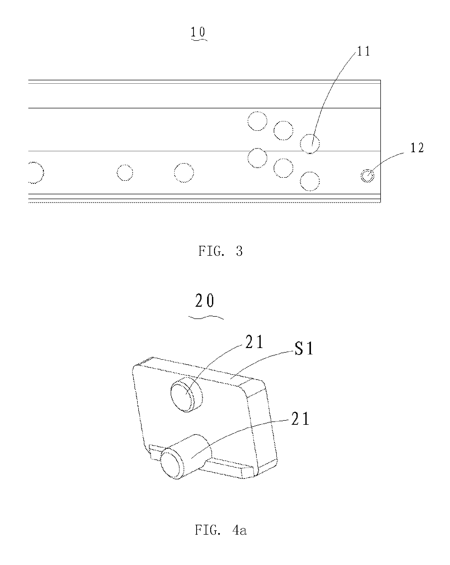
[0025]With reference to FIG. 1, a liquid crystal panel fixing assembly is used for limiting and fixing a liquid crystal panel 1 of a display device. The liquid crystal panel fixing assembly includes a frame structure 10 having a rectangular shape, and multiple position-limiting blocks 20 disposed on the frame structure 10. The frame structure 10 is used for supporting the liquid crystal panel 1. Two adjacent edges of the frame structure 10 respectively provide with multiple fixing portions 11 having different distances relative to an inner side surface of the frame structure 10. The position-limiting blocks 20 are selectively fixed at a group of the fixing portions 11. The position-limiting blocks 20 are disposed at intervals in order to form a placement region for different display panels. A bottom surface of the display panel 1 is disposed on the frame structure 10, and side walls of the liquid crystal panel 1 are clamped and limited by the position-limiting blocks 20. The frame s...

embodiment 2

[0031]With combined reference to FIG. 5, in addition, distances of two protrusion columns 21 with respect to an inner side wall S1 and an outer side wall S2 (shown in FIG. 1) of the position-limiting block 20 are not equal. That is, a distance between the protrusion column 21 located at an inner side and the inner side wall S1 is not equal to a distance between the protrusion column 21 at an outer side and the outer side wall S2. Through above arrangement, when a position-limiting block 20 is pulled out, rotated 180 degrees (i.e. positions of the outer side wall S2 and the inner side wall S1 are exchanged) and fixed into a same fixing portion 11, a distance between the position-limiting blocks 20 located on two opposite side walls of the frame structure 10 is changed so that a size of a placement region of a liquid crystal panel enclosed by multiple position-limiting blocks 20 is changed. Accordingly, a size range of the liquid crystal panels that is compatible with the same liquid ...


PUM

PropertyMeasurementUnit
distancesaaaaaaaaaa
lengthaaaaaaaaaa
sizeaaaaaaaaaa

Abstract

A liquid crystal panel fixing assembly and a display device are disclosed. The assembly includes a frame structure having a rectangular shape and multiple position-limiting blocks. The frame structure is used for supporting a liquid crystal panel. Two adjacent edges of the frame structure respectively provide with multiple fixing portions having different distances relative to an inner side surface of the frame structure. The multiple position-limiting blocks are selectively fixed at a group of the fixing portions in order to form a placement region for different display panels. Using the frame structure to support the liquid crystal panel, and through adjusting locations of the position-limiting blocks in order to fix liquid crystal panels having different sizes, the cost for developing different backlight modules for different liquid crystal panels is reduced, and the compatibility of a backlight module is increased.

Description

BACKGROUND OF THE INVENTION[0001]1. Field of the Invention[0002]The present invention relates to a display technology field, and more particular to a liquid crystal panel fixing assembly and a display device.[0003]2. Description of Related Art[0004]In the development of a liquid crystal panel, because of the consideration for the need of difference, panels having a same display size may have different external sizes. Specially, different panel manufacturers utilize different trace technology, and external sizes of panels are more different. In the development of a backlight module, in order to reduce a development process of a mold, reduce development cost, shorten development period, a backlight module that can be compatible with liquid crystal panels having different external sizes is required. However, the conventional fixing method cannot satisfy the above requirement.SUMMARY OF THE INVENTION[0005]In view of the deficiencies of the conventional art, the present invention provide...

Claims


Application Information

Patent Timeline
Patent Type & Authority Applications(United States)
IPC IPC(8): G02F1/1333
CPCG02F1/133308G02F2001/133317G02F2001/133322G02F2001/13332G02F2201/46G02F2201/465G02F1/133322G02F1/133317
Inventor LI, QUANHSIAO, YUCHUNTANG, GUOFU
Owner SHENZHEN CHINA STAR OPTOELECTRONICS TECH CO LTD
Why Eureka
Try Eureka