Motor Vehicle Subframe

Inactive Publication Date: 2017-02-23
FORD GLOBAL TECH LLC
View PDF7 Cites 7 Cited by
  • Summary
  • Abstract
  • Description
  • Claims
  • Application Information

AI Technical Summary

Benefits of technology

The patent text describes a way to compensate for the rolling movements of a vehicle structure by using a stabilizer. The stabilizer is mounted on a crossmember wall and can rotate within stabilizer bearings. The position of the stabilizer bearings can be inside or outside of the crossmember wall. This design helps reduce the movement of the vehicle structure and improve its stability.

Problems solved by technology

In modern rear wheel suspensions of motor vehicles, space is often limited near the rear lower floor.
Further, in a longitudinal direction of the vehicle, the arrangement in particular of a subframe of a rear wheel suspension including a stabilizer system and a spare wheel recess in the floor of the vehicle for receiving a full-size spare wheel may lead to a considerable problem.

Method used


Image

  • Motor Vehicle Subframe
  • Motor Vehicle Subframe
  • Motor Vehicle Subframe

Examples


Embodiment Construction

[0017]The following description of the preferred embodiment(s) is merely exemplary in nature and is in no way intended to limit the invention, its application, or uses.

[0018]The various figures use the same reference numerals for parts that are the same in terms of the function thereof so that generally these parts are described only once.

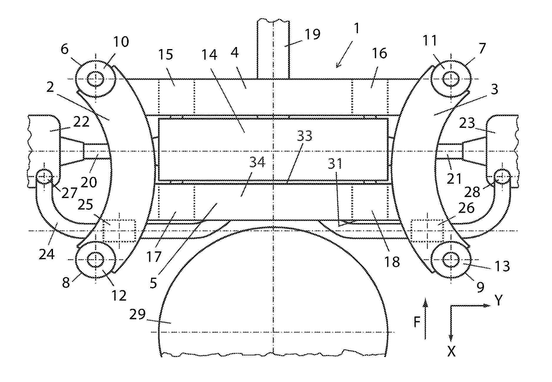
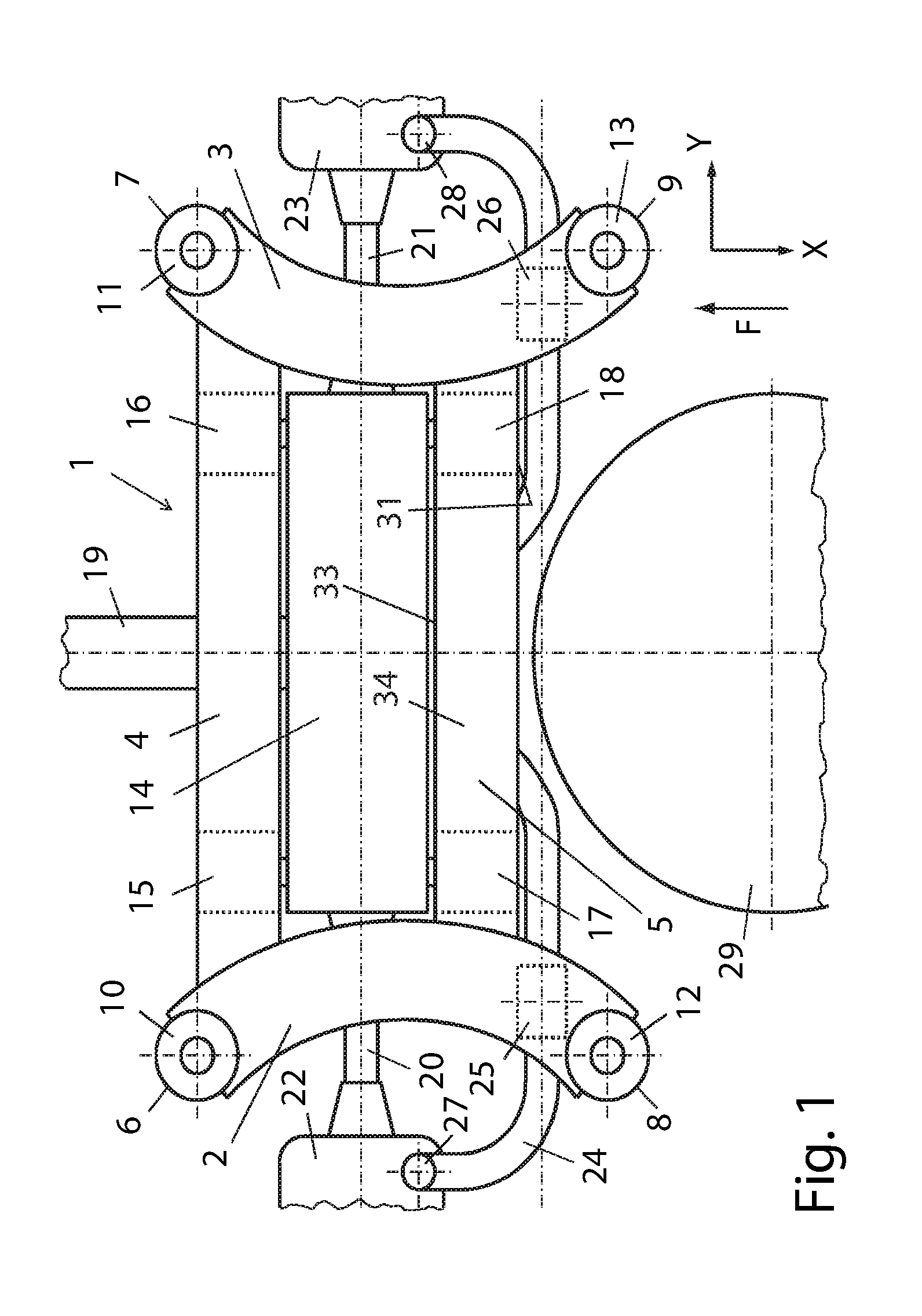
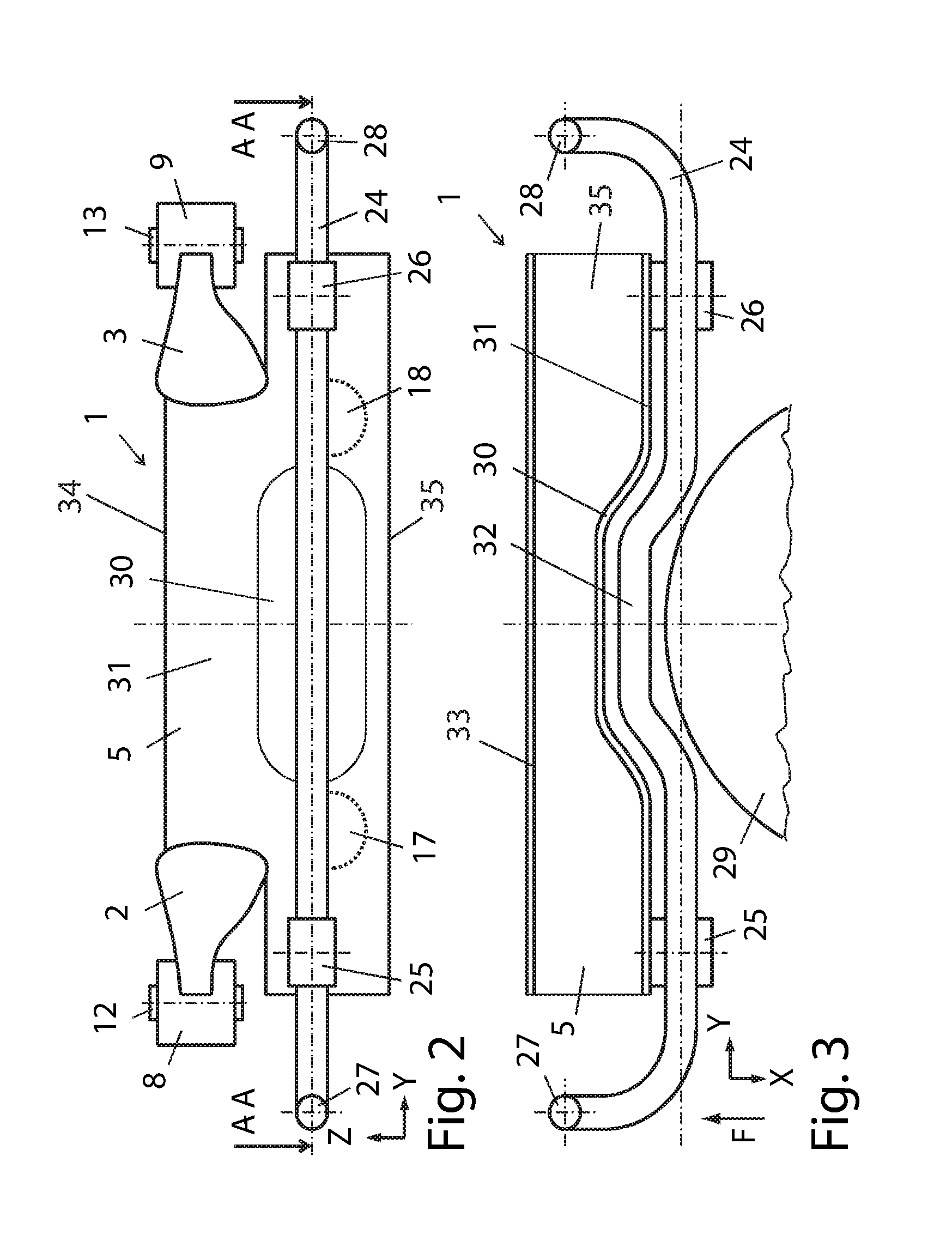
[0019]FIG. 1 shows schematically a plan view of an exemplary embodiment of a subframe 1 for a vehicle (not shown) according to the invention. The forward direction of travel of the vehicle is generally indicated in FIG. 1 by F, a vehicle longitudinal direction by X, a vehicle transverse direction by Y, and a vehicle vertical direction by Z, see FIG. 2.

[0020]FIG. 1 shows a subframe 1 including a left-hand longitudinal member 2 extending in the vehicle longitudinal direction X and a right-hand longitudinal member 3 extending in the vehicle longitudinal direction X and spaced apart from the longitudinal member 2. The longitudinal members 2, 3 may, for...


PUM


Abstract

A vehicle subframe for supporting wheel suspension elements and for mounting a stabilizer extending in a vehicle transverse direction. The subframe including two spaced longitudinal members extending in the vehicle longitudinal direction connected by at least one crossmember extending in the vehicle transverse direction. The crossmember having a hollow profile with a rear crossmember wall facing the stabilizer. The rear crossmember wall having an indentation extending in a longitudinal direction of the crossmember. The indentation faces the interior of the hollow profile wherein the stabilizer partially extends into the indentation.

Description

CROSS-REFERENCE TO RELATED APPLICATIONS[0001]Not Applicable.BACKGROUND OF THE INVENTION[0002]1. Field of the Invention[0003]The invention relates to a motor vehicle; and more specifically, to a motor vehicle subframe.[0004]2. Description of Related Art[0005]Vehicle subframes are often formed from a frame construction including two parallel, spaced apart longitudinal members connected together in the manner of a frame by two parallel, spaced apart cross members. The subframe serves, for example, for attaching wheel-guiding control arms, wherein the control arms are connected on one side to the subframe and, on the other side, to a wheel carrier receiving the wheel. The subframe may also receive additional vehicle components, for example a transfer gearbox, intermediate gear, differential gear, or differential. The subframe may be connected as a whole to the vehicle structure, wherein the subframe is fastened by a plurality of bearings, preferably four bearings, to the vehicle structu...

Claims


Application Information

Patent Timeline
IPC IPC(8): B62D21/11B60G21/055
CPCB60G21/0551B62D21/11B60G2202/135B60G2204/15B62D21/02B60G2204/1222
Inventor WOLF-MONHEIM, FRIEDRICH PETER
Owner FORD GLOBAL TECH LLC
Why Eureka
Try Eureka