Vehicle Spoke Wheel Weight

a technology of spoke wheels and spoke wheels, applied in the direction of springs/dampers, vibration suppression adjustments, mechanical equipment, etc., can solve the problems of unbalanced condition, unbalanced wheels, negative and even unsafe vibrations,

Inactive Publication Date: 2017-02-23
KIBBLEWHITE PRECISION MACHINING INC
View PDF1 Cites 1 Cited by
  • Summary
  • Abstract
  • Description
  • Claims
  • Application Information

AI Technical Summary

Benefits of technology

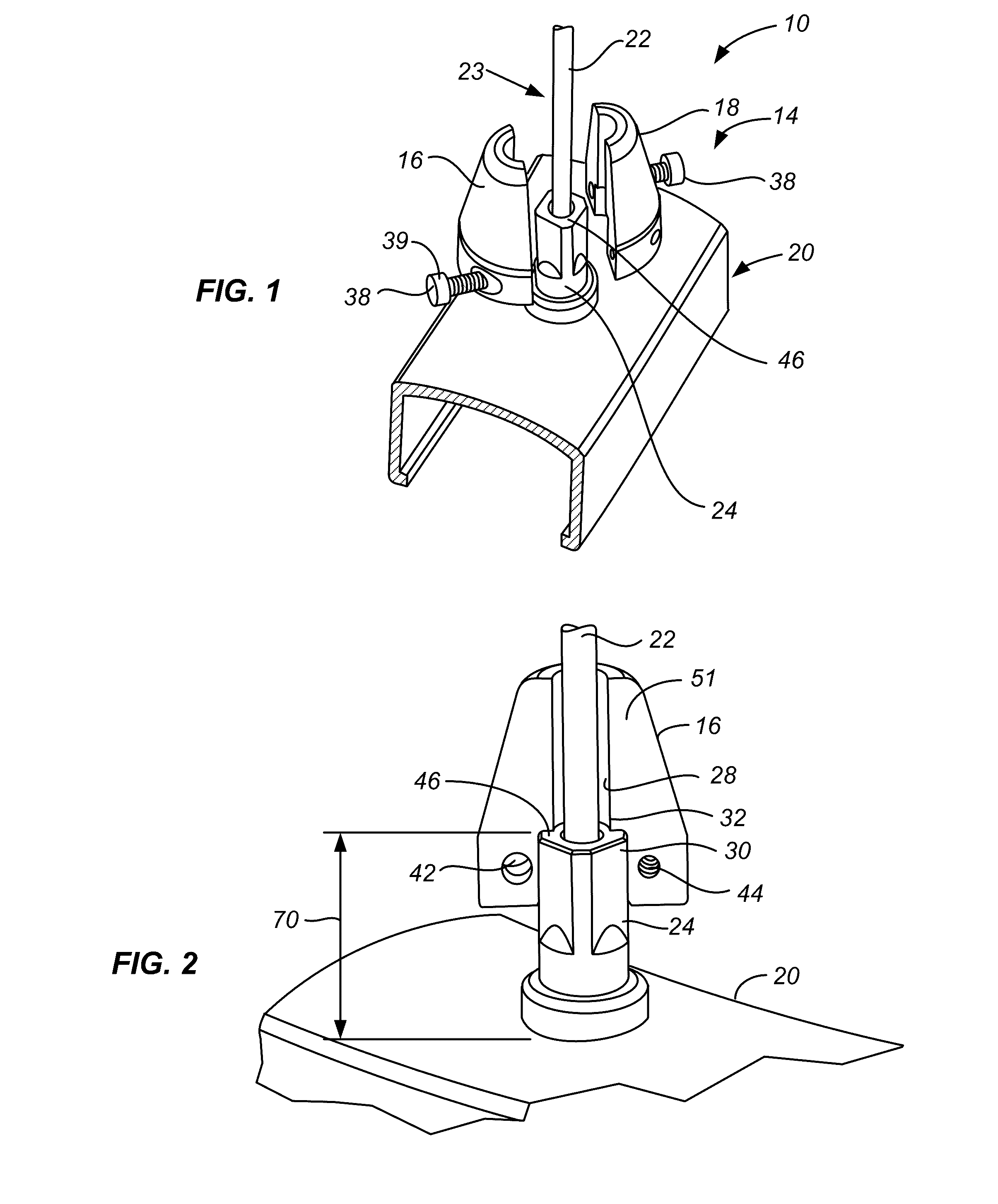
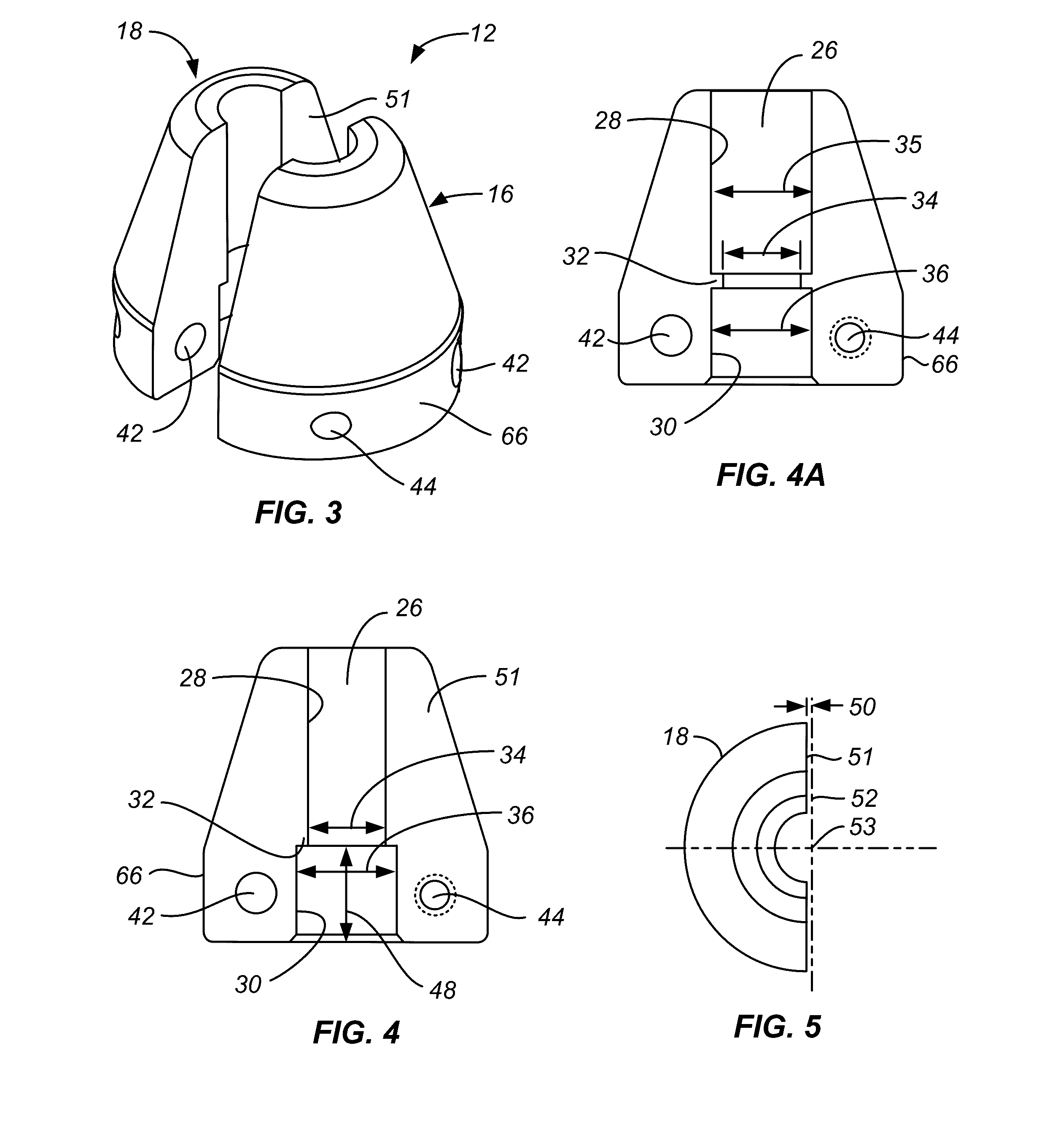
[0009]Examples of the vehicle spoke wheel weight can include one or more the following. The upper and lower bore surfaces and the shoulder of each body part can define generally semi-cylindrical surfaces of less than a full semicircle. A shim material can be placeable at the upper bore surfaces. The fastener assembly can include a threaded fastener assembly. When the first and second body parts are in the mounting orientation, the first and second body parts can define a longitudinally extending gap therebetween, and the fastener assembly can include a fastener element extendable between the first and second body parts and through the longitudinally extending gap. When the first and second body parts are in the mounting orientation, the first and second body parts can define first and second longitudinally extending gaps therebetween, and the fastener assembly can include a fastener element extendable between the first and second body parts and through each of the longitudinally extending gaps. The lateral dimensions of the shoulder and the upper bore surface can be the same.
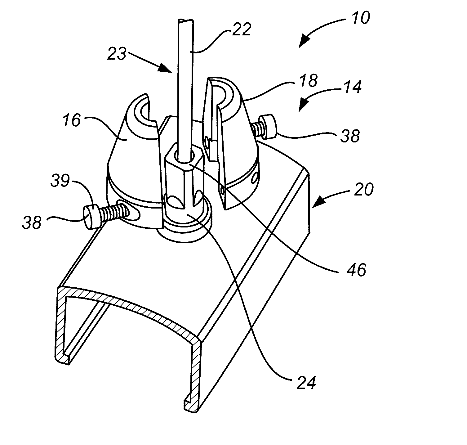
[0010]An example of a spoked wheel assembly includes a circular wheel rim, a spoke / nipple assembly, and a vehicle spoke wheel weight. The spoke / nipple assembly includes a spoke nipple mounted to the wheel rim. The spoke nipple has an outer end from which a spoke extends radially inwardly, the outer end having a lateral dimension. The vehicle spoke wheel weight includes a body having first and second body parts, and a fastener assembly. Each body part has a central bore has an upper bore surface, a lower bore surface and a shoulder connecting the upper and lower bore surfaces. The upper and lower bore surfaces and the shoulder have lateral dimensions with the lateral dimension of the lower bore surface being larger than the lateral dimension of the shoulder. The lateral dimension of the shoulder is smaller than the lateral dimension of the outer end of the nipple. The first and second body parts are placeable in a mounting orientation with the central bores of each located opposite one another with: the upper bore surfaces opposite the spoke; the lower bore surfaces opposite the nipple; the shoulders contacting the outer end of the spoke nipple; and the body being spaced apart from the wheel rim. The fastener assembly secures the first and second body parts to one another when in the mounting orientation thereby biasing the lower bore surface against the nipple to secure the vehicle spoke wheel weight to the spoke / nipple assembly.
[0011]A method for making a vehicle spoke wheel weight includes forming a body and creating a fastener assembly. The vehicle spoke wheel weight is of the type for use with a spoke / nipple assembly including a spoke nipple mounted to a circular wheel rim, the spoke nipple having an outer end from which a spoke extends radially inwardly. The body is formed with first and second body parts with each body part having a face surface. The body forming step includes creating a central bore in each body part extending from the face surface, the central bore having an upper bore surface, a lower bore surface and a shoulder connecting the upper and lower bore surfaces, the lower bore surface having a larger lateral dimension than the lateral dimension of the shoulder. The body forming step also includes forming the central bore so that the central bore of each body part defines a surface of less than a full semi-circle. The fastener assembly creating step includes creating a fastener assembly for securing the first and second body parts to one another when the first and second body parts are placed in a mounting orientation with the face surfaces and the central bores of each opposite one another. The body forming step further includes configuring the first and second body parts so that the lower bore surface can securely engage a range of sizes of spoke nipples when secured thereto by the fastener assembly.
[0012]Some examples of the vehicle spoke wheel weight making method can include one or more the following. The shoulder can be configured to be placeable against an outer end of a spoke nipple, the spoke nipple having a height. The height of the lower bore surface can be limited to be less than the height of the spoke nipple so that the body is spaced apart from the wheel rim. The first and second body parts can define a longitudinally extending gap between the face surfaces when in the mounting orientation; the first and second body parts configuring step can include sizing of the gap and sizing of the lateral dimensions of the lower bore surfaces so that the lower bore surfaces of the first and second body parts can be biased against the spoke nipple by the fastener assembly over said range of sizes of spoke nipples.

Problems solved by technology

An unbalanced condition occurs when the center of gravity of the wheel is not located precisely upon its axis of rotation.
Small variations in symmetry and mass can cause wheels to be unbalanced.
In this condition, the normal operational motion of spinning can create negative and even unsafe vibrations that can be perceived by the operator and affect performance.
These vibrations can increase in severity as the speed of the wheel increases.
However many recent state and local regulations have severely limited the amount of lead acceptable for use in wheel weights, making many current crimpable, lead-containing products illegal.

Method used


Image

  • Vehicle Spoke Wheel Weight
  • Vehicle Spoke Wheel Weight
  • Vehicle Spoke Wheel Weight

Examples


Embodiment Construction

[0024]The following description will typically be with reference to specific structural embodiments and methods. It is to be understood that there is no intention to-be limited to the specifically disclosed embodiments and methods but that other features, elements, methods and embodiments may be used for implementations of this disclosure. Preferred embodiments are described to illustrate the technology disclosed, not to limit its scope, which is defined by the claims. Those of ordinary skill in the art will recognize a variety of equivalent variations on the description which follows. Unless otherwise stated, in this application specified relationships, such as parallel to, aligned with, or in the same plane as, mean that the specified relationships are within limitations of manufacturing processes and within manufacturing variations. When components are described as being coupled, connected, being in contact or contacting one another, they need not be physically directly touching ...


PUM


Abstract

A vehicle spoke wheel weight includes a body, with first and second body parts, and a fastener assembly. Each body part includes a central bore having an upper bore surface, a lower bore surface and a shoulder connecting the upper and lower bore surfaces. The lateral dimension of the lower bore surface is larger than the lateral dimension of the shoulder. The first and second body parts are placeable in a mounting orientation with the central bores of each opposite one another and securable to one another by the fastener assembly. The upper and lower bore surfaces and the shoulder of each body part can define generally semi-cylindrical surfaces of less than a full semicircle. A shim material can be placeable at the upper bore surfaces. A method for making a vehicle spoke wheel weight includes forming a body and creating a fastener assembly.

Description

CROSS-REFERENCE TO OTHER APPLICATIONS[0001]This application claims the benefit of U.S. provisional patent application No. 62 / 207,758 filed 20 Aug. 2015.[0002]This application is related to U.S. design patent application 29 / 541,755, filed 7 Oct. 2015.FEDERALLY SPONSORED RESEARCH OR DEVELOPMENT[0003]None.BACKGROUND OF THE INVENTION[0004]The subject matter discussed in this section should not be assumed to be prior art merely as a result of its mention in this section. Similarly, a problem mentioned in this section or associated with the subject matter provided as background should not be assumed to have been previously recognized in the prior art. The subject matter in this section merely represents different approaches, which in and of themselves may also correspond to implementations of the claimed technology.[0005]For optimal operation, a wheel is required to be round and balanced. An unbalanced condition occurs when the center of gravity of the wheel is not located precisely upon ...

Claims


Application Information

Patent Timeline
Patent Type & Authority Applications(United States)
IPC IPC(8): F16F15/32F16F15/34
CPCF16F15/345F16F15/326
Inventor KIBBLEWHITE, WILLIAM FRANCISHARRINGTON, JACOB WINSLOW
Owner KIBBLEWHITE PRECISION MACHINING INC
Why Eureka
Try Eureka