System and process for formation of extrusion products

a technology of extrusion products and process, applied in the field of metal product production, can solve the problems of increasing cost, affecting the quality of extrusion products,

Active Publication Date: 2017-03-02
BATTELLE MEMORIAL INST
View PDF0 Cites 14 Cited by
  • Summary
  • Abstract
  • Description
  • Claims
  • Application Information

AI Technical Summary

Benefits of technology

[0007]In some embodiments the scroll face includes raised ridges that extend upward from the face of the extrusion die to form flow path channels that extend from the outer edge of the scroll toward the center of the die so as to draw plasticized billet material from the outer edge of the billet toward the extrusion orifice as the scroll spins. These ridges may be arranged in a pattern having comprising at least one start on the scroll face configured to engage the plasticized material during operation. In other embodiments there are two or even three starts. The some embodiments a container defines a chamber with a fixed mandrel that is placed at a central position within the chamber. The mandrel is configured to connect to and mount upon the billet within the chamber prior to extrusion. When the mandrel is present the extrusion products that are created are generally hollow or have hollow portions.
[0008]The extrusion process of some embodiments of the invention comprises the steps of simultaneously applying a rotational shearing force and an axial extrusion force to an end of a billet while contacting one an end of the billet with a scroll face configured to engage the end of the billet and move plasticized billet material toward an orifice of the extrusion die whereby the plastically deformed billet material flows substantially perpendicularly from an outer edge of the billet through the orifice of the extrusion die to form to form forming an extrusion product with microstructure grains being about one-half the size of the grains in the billet prior to extrusion. In some applications, the axial extrusion force per unit area is less than 100 MPa, sometimes less than 50 MPa, and sometimes even less than 25 MPa, and the temperature of the billet is less than 100° C. Typically, the feed rate is less than 0.2 inches (0.51 cm) per minute and the rotational shearing force is generated from spinning the die or the billet at a rate between 100 rpm to 500 rpm. Typically, the resultant products created from such a process have various desired features including microstructure grains that can be non-parallelly oriented with respect to the extrusion axis, grains that can be equi-axial in all three dimensions, and microstructures with grains that can have sizes below about 10 microns, sometimes below about 5 microns, and sometimes even less than or equal to about 1 micron.

Problems solved by technology

However, problems exist in attempting to form products, particularly hollow products from these harder metal alloys.
For example, harder alloys typically require substantially larger forces for extrusion and routinely generate extrusion products with inconsistent and non-uniform microstructures which lead to problems in strength and reliability.
Conventional processes for forming such devices can also highly energy consumptive processing or multiple steps to achieve desired features which can adds significant costs.

Method used


Image

  • System and process for formation of extrusion products
  • System and process for formation of extrusion products
  • System and process for formation of extrusion products

Examples


example 1

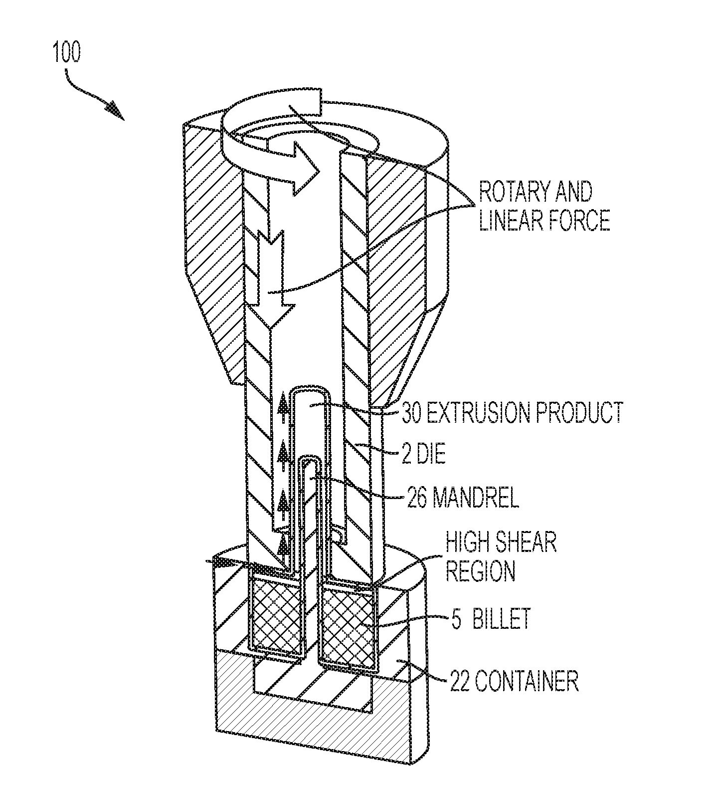
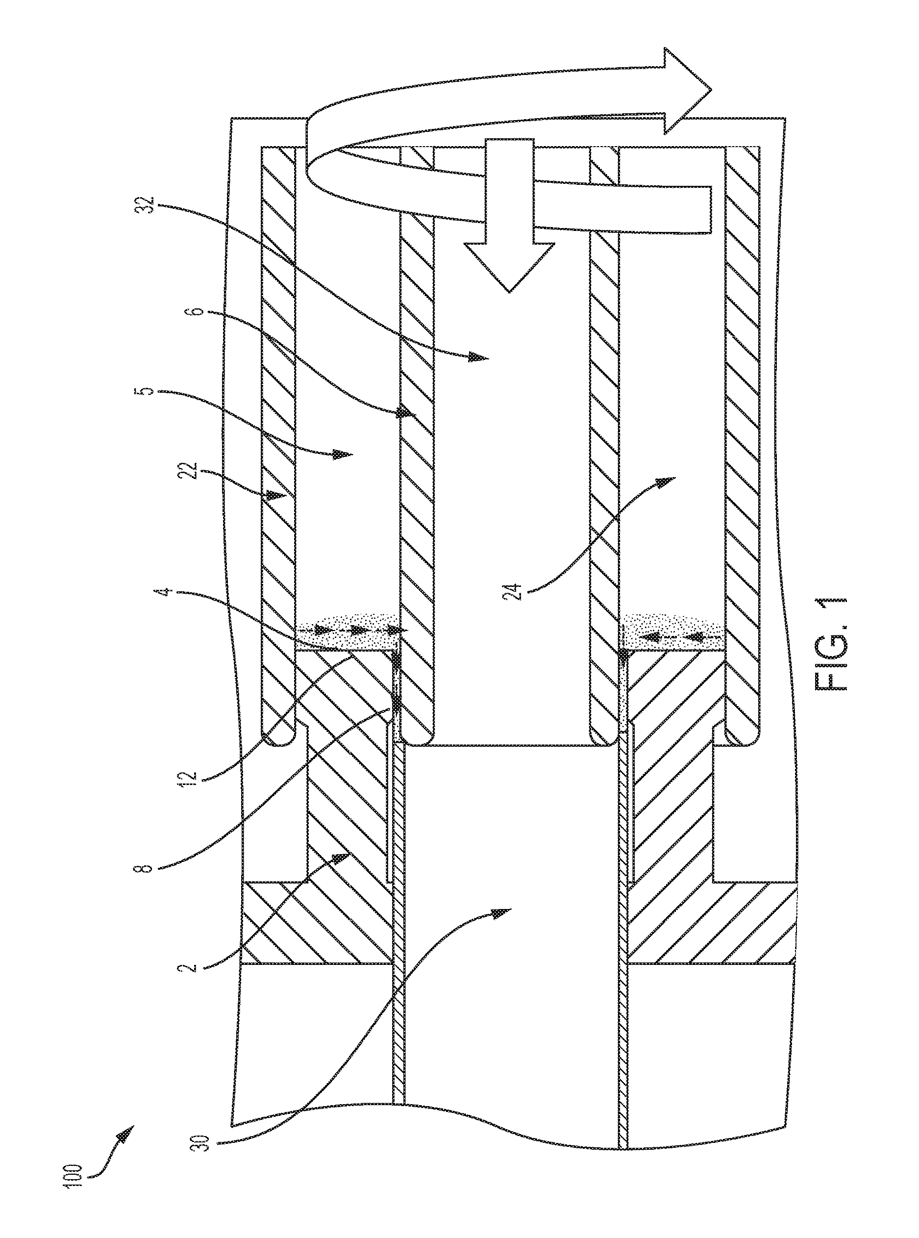
[0025]In one set of experiments, a direct extrusion assembly similar to that shown in FIG. 1 was used to extrude an exemplary magnesium alloy (ZK60A-T5) to produce exemplary tubes by direct extrusion. The extrusion die 2 included an inner diameter (ID) of 50.8 mm that determined the outer diameter (OD) of the resulting extrusion product 30. An integrated container 22 and mandrel 26 assembly was used. In the exemplary embodiment, container 22 included an ID of 88.9 mm and the mandrel 26 included an OD of 47.8 mm. The difference in the radius between the ID of the extrusion die 2 and OD of the mandrel 26 was 1.52 mm, which determined the wall thickness of the extrusion product 30. Hollow billets 5 of the ZK60 alloy were machined from a round bar stock, and then extruded to form tubes 30 with an OD of 88.8 mm, an ID of 47.9 mm, and a length of 113 mm. Billets were not preheated, and ambient conditions in the processing location were less than 100° C. Cylindrical pockets (e.g., four) we...

example 2

[0026]In another set of experiments, an indirect extrusion assembly similar to that shown in FIG. 3 was used to extrude another exemplary magnesium alloy (AZ91E) to prepare thin-walled tubing by indirect extrusion. Melt spun, rapidly solidified flakes of the AZ91E alloy were formed into a billet 5 and loaded into a cylindrical container 22 (I.D. of 31.8 mm; Height of 21.0 mm). Face 12 of the extrusion die 2 included a single spiral scroll 4 that promoted flow of plasticized material through the centrally positioned extrusion orifice 8 (7.5 mm diameter) into the inner bore (throat) of the extrusion die 2. The extrusion die 2 included a 6.4 mm long throat, and a 90° relief to minimize friction between the inner wall of the die throat and the extrusion product 30. Plasticized material was then back-extruded through a 0.75 mm gap disposed between the exterior surface of the mandrel 26 and the inner wall of the die throat, resulting in formation of the tube. Rotational speed and axial ex...

example 3

[0028]TABLE 1 lists compositions of alloy billets and process parameters employed in selected extrusion tests using an indirect extrusion assembly similar to the arrangement shown in FIG. 3.

TABLE 1FeedExtru-RotationRatesionTestSpeed(inches / Force#Alloy(rpm)min)(lbf)1Mg—2Si5000.1520002Mg—7Si5000.1520003AZ31F5000.1520004ZK60-T55000.1520005AZ915000.152000

[0029]TABLE 2 lists dimensions of exemplary hollow extrusion products obtained from extrusion tests listed in Table 1.

TABLE 2Extru-sionExtru-RateTestO.D.I.D.sion(Inches / #AlloyInchesmmInchesmmRatiomin)1Mg—2Si0.2927.420.2315.8748.9777.3472Mg—7Si0.2917.390.2335.9251.4127.7123AZ31F0.2917.390.2325.8950.6377.5964ZK60-TS0.2937.440.235.8447.4227.113AVERAGE0.2927.410.2325.8849.6127.442STD. DEV.9.5E−42.4E−21.3E−30.0331.7790.267

[0030]Extrusion rate for these tests was about 7.5 inches per minute, but rates are not limited. For example, rates can vary based on selected processing parameters, for example, from several inches per minute to several fe...


PUM

PropertyMeasurementUnit
temperatureaaaaaaaaaa
sizesaaaaaaaaaa
sizesaaaaaaaaaa

Abstract

Devices and processes for performing shear-assisted extrusion include a rotatable extrusion die with a scroll face configured to draw plasticized material from an outer edge of a billet generally perpendicularly toward an extrusion orifice while the extrusion die assembly simultaneously applies a rotational shear and axial extrusion force to the billet.

Description

CROSS REFERENCE TO RELATED APPLICATIONS[0001]This application is a Continuation-In-Part of pending U.S. Provisional Application No. 62 / 313,500 filed 25 Mar. 2016, and pending U.S. patent application Ser. No. 14 / 222,468 filed 21 Mar. 2014 which claims priority from U.S. Provisional Application No. 61 / 804,560 filed 22 Mar. 2013, now abandoned, which are incorporated in their entirety herein.STATEMENT REGARDING RIGHTS TO INVENTION MADE UNDER FEDERALLY-SPONSORED RESEARCH AND DEVELOPMENT[0002]This invention was made with Government support under Contract DE-AC05-76RL01830 awarded by the U.S. Department of Energy. The Government has certain rights in the invention.FIELD OF THE INVENTION[0003]The present invention relates generally to production of metal products more particularly to shear-assisted extrusion systems and processes for producing light-weight, high-performance extrusion products.BACKGROUND OF THE INVENTION[0004]A need exists for light-weight metal products that can be used to...

Claims


Application Information

Patent Timeline
Patent Type & Authority Applications(United States)
IPC IPC(8): B21C23/00B21C23/14
CPCB21C23/14B21C23/002B21C29/003B21C23/212B21C23/218B21C27/00B21C23/08B21C25/02
Inventor LAVENDER, CURTIS A.JOSHI, VINEET V.GRANT, GLENN J.JANA, SAUMYADEEPWHALEN, SCOTT A.DARSELL, JENS T.OVERMAN, NICOLE R.
Owner BATTELLE MEMORIAL INST
Why Eureka
Try Eureka