
Audio processing device

a processing device and audio technology, applied in the direction of loudspeaker signal distribution, electric devices, stereophonic systems, etc., can solve the problems of dsd data not being reproduced and outputing to the zone2 room

Inactive Publication Date: 2017-03-02
ONKYO TECH KK
View PDF3 Cites 0 Cited by
  • Summary
  • Abstract
  • Description
  • Claims
  • Application Information

AI Technical Summary

Benefits of technology

The patent aims to prevent interruptions in audio signals when using a second reproduction device and a first D / A converter. The solution presented is to connect the second reproduction device with a second D / A converter by a switch, while the first reproduction device is connected to the first D / A converter by another switch. This prevents interruptions in the audio signal caused by the switches and ensures the smooth reproduction of the audio signals.

Problems solved by technology

For this reason, there is a problem that the DSD data cannot be reproduced and output to the Zone2 room.

Method used


Image

  • Audio processing device
  • Audio processing device
  • Audio processing device

Examples


first embodiment

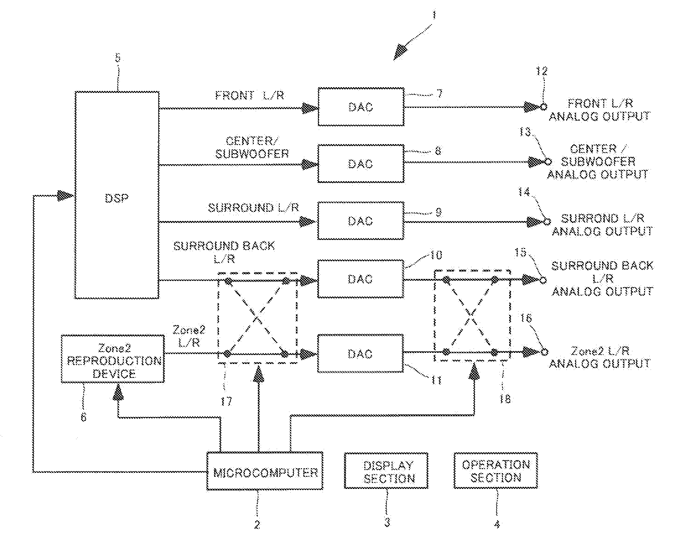
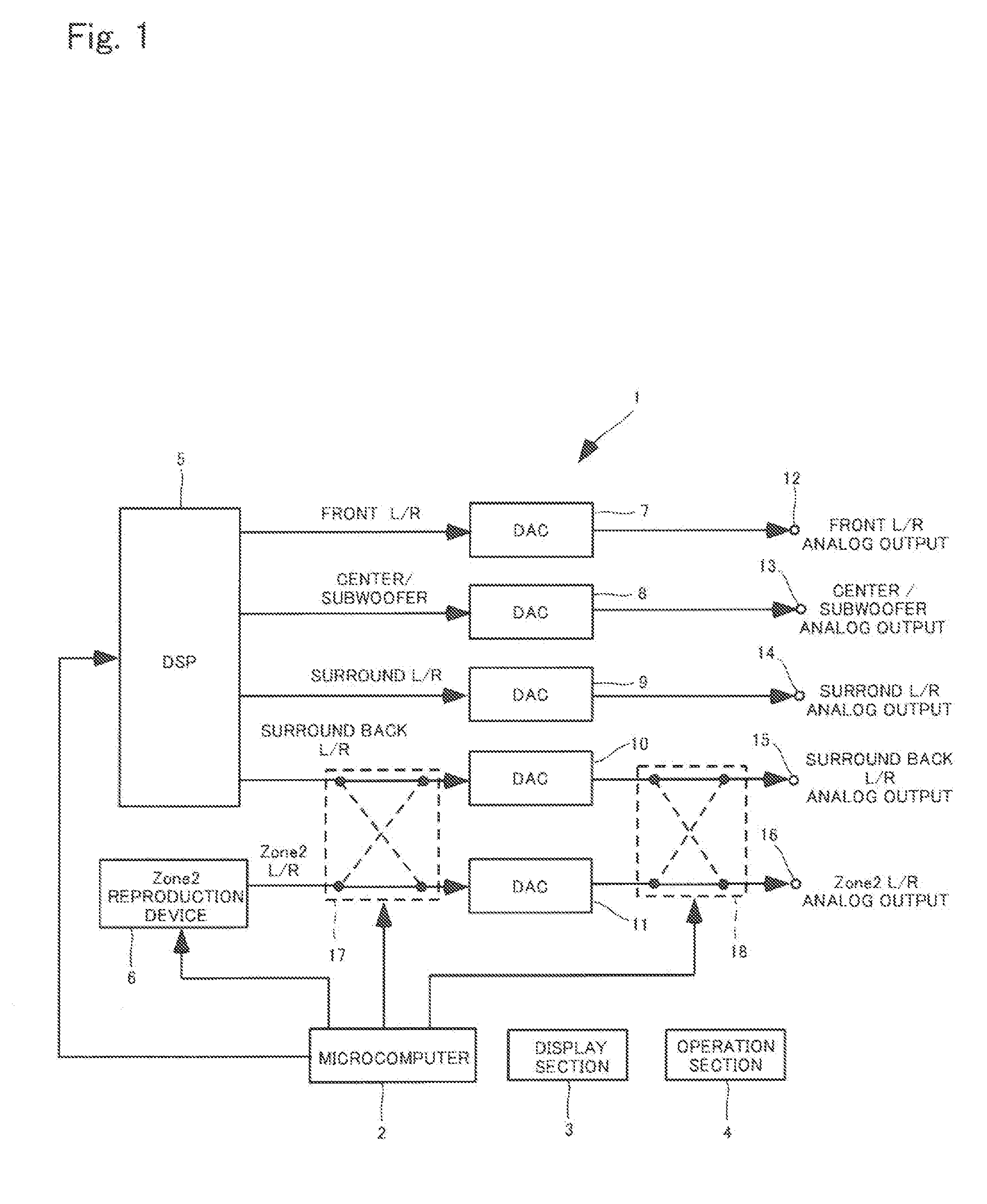
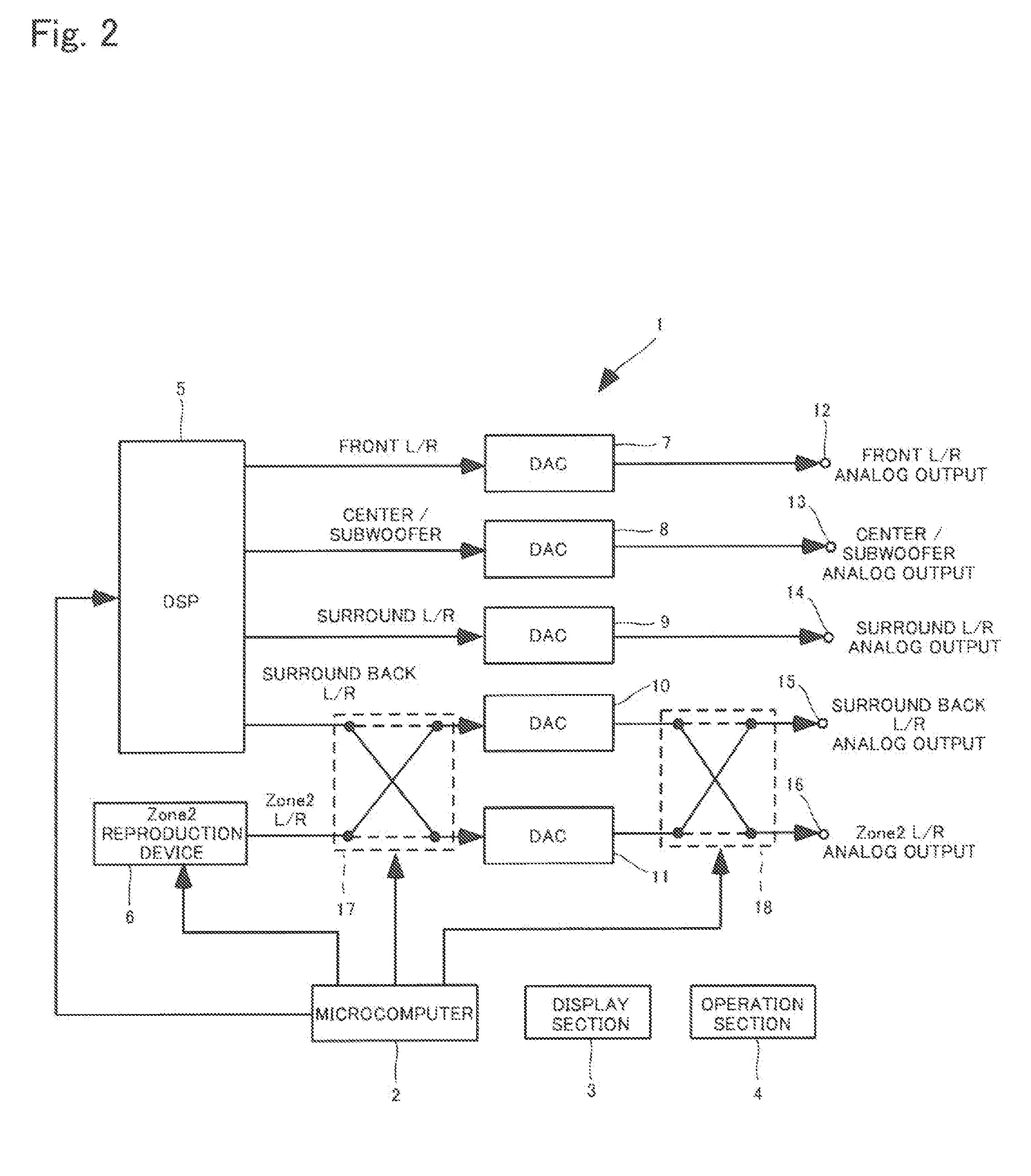
[0034]Each of FIG. 1 and FIG. 2 is a block diagram illustrating a configuration of an AV receiver according to a first embodiment of the present invention. An AV receiver 1 has a main output route and a Zone2 output route. The AV receiver 1 performs audio signal processing to a digital audio signal and outputs an analog audio signal to main speakers that are located in a main room (main output route (first output route)). Further, the AV receiver 1 performs audio signal processing to the digital audio signal and outputs the analog audio signal to Zone2 speakers (sub speakers) that are located in a Zone2 room (sub room) (Zone2 output route (second output route)).

[0035]The AV receiver 1 can perform audio signal processing to a 7.1 channels digital audio signal. As illustrated in FIG. 1 and FIG. 2, the AV receiver 1 includes a microcomputer 2, a display section 3, an operation section 4, a DSP 5, a Zone2 reproduction device 6, DACs 7 to 11, analog output terminals 12 to 16, and switche...

second embodiment

[0052]Each of FIG. 3 and FIG. 4 is a block diagram of a configuration of an AV receiver according to a second embodiment of the present invention. Configuration that the AV receiver 1 according to the second embodiment does not include the DAC 10 for surround back is mainly different compared with the AV receiver 1 according to the first embodiment. Therefore, the AV receiver 1 includes three DACs 7 to 9 and can perform audio signal processing to a 5.1 channels digital audio signal. The configuration different from the first embodiment is hereinafter described.

[0053]The switch 17 connects a surround port of the DSP 5 with the DAC 9 or the DAC 11. Further, the switch 17 connects the Zone2 reproduction device 6 with the DAC 9 or the DAC 11. The switch 18 connects the DAC 9 with the surround analog output terminal 14 or the Zone2 analog output terminal 16. The surround port is a port that outputs the surround left digital audio signal and the surround right digital audio signal.

[0054]I...


PUM


Abstract

In an audio processing device having a first output route and a second output route, to be able to reproduce the same audio signal as the first output rote at the second output route.A microcomputer 2 connects a Zone2 reproduction device 6 with a DAC 10 for a surround back by a switch 17 and the DAC 10 for the surround back with a surround back analog output terminal 15 by a switch 18 in case that the DSD data is reproduced at a Zone2 output route.

Description

BACKGROUND OF THE INVENTION[0001]1. Field of the Invention[0002]The present invention relates to an audio processing device that performs audio signal processing to a digital audio signal.[0003]2. Description of the Related Art[0004]As an audio processing device that performs audio signal processing such as D / A conversion and amplification to a digital audio signal, there is an AV receiver. The AV receiver that is described in JP 2013-046265 A performs audio signal processing to the digital audio signal and outputs an analog audio signal to main speakers that are located in a main room (main output route (first output route)). The AV receiver that is described in JP 2013-046265A performs audio signal processing to the digital audio signal and outputs the analog audio signal to Zone2 speakers (sub speakers) that are located in a Zone2 room (sub room) (Zone2 output route (second output route)).[0005]FIG. 5 is a block diagram illustrating a configuration of a conventional AV receiver. ...

Claims


Application Information

Patent Timeline
Patent Type & Authority Applications(United States)
IPC IPC(8): H04S3/00H04S1/00
CPCH04S3/008H04S2400/01H04S1/007H04R3/12H04R2227/005
Inventor KOBAYASHI, JUNICHIKOAZE, SUSUMU
Owner ONKYO TECH KK
Learn More