Image control apparatus

a technology of image control and control apparatus, which is applied in the direction of optical viewing, vehicle components, instruments, etc., can solve the problems of inability the inability of the interior rearview mirror to be used to see the surrounding area behind the vehicle, and the inability of the user to see the situation of the rear area of the vehicl

Inactive Publication Date: 2017-03-23
FUJITSU GENERAL LTD
View PDF7 Cites 8 Cited by
  • Summary
  • Abstract
  • Description
  • Claims
  • Application Information

AI Technical Summary

Problems solved by technology

However, even if the driver uses the interior rearview mirror, there is a case where it is difficult for the driver to see the surrounding area behind the vehicle because driver's view is blocked by luggage and the like in a rear area of the cabin of the vehicle.
Moreover, in a case of a truck having a container and the like, there is a case where the interior rearview mirror cannot be used to see the surrounding area behind the vehicle.
Since the foregoing image display system does not display an image showing the cabin of the vehicle, it is impossible for the user to see a situation of the rear area of the cabin of the vehicle.
However, there are cases where the user feels it troublesome to change the operation modes.
Thus, the driver may continue driving of the vehicle while having the image display system in an operation mode inappropriate to a state of the vehicle.

Method used


Image

  • Image control apparatus
  • Image control apparatus
  • Image control apparatus

Examples


first embodiment

1. First Embodiment

1-1. Outline of Image Display System

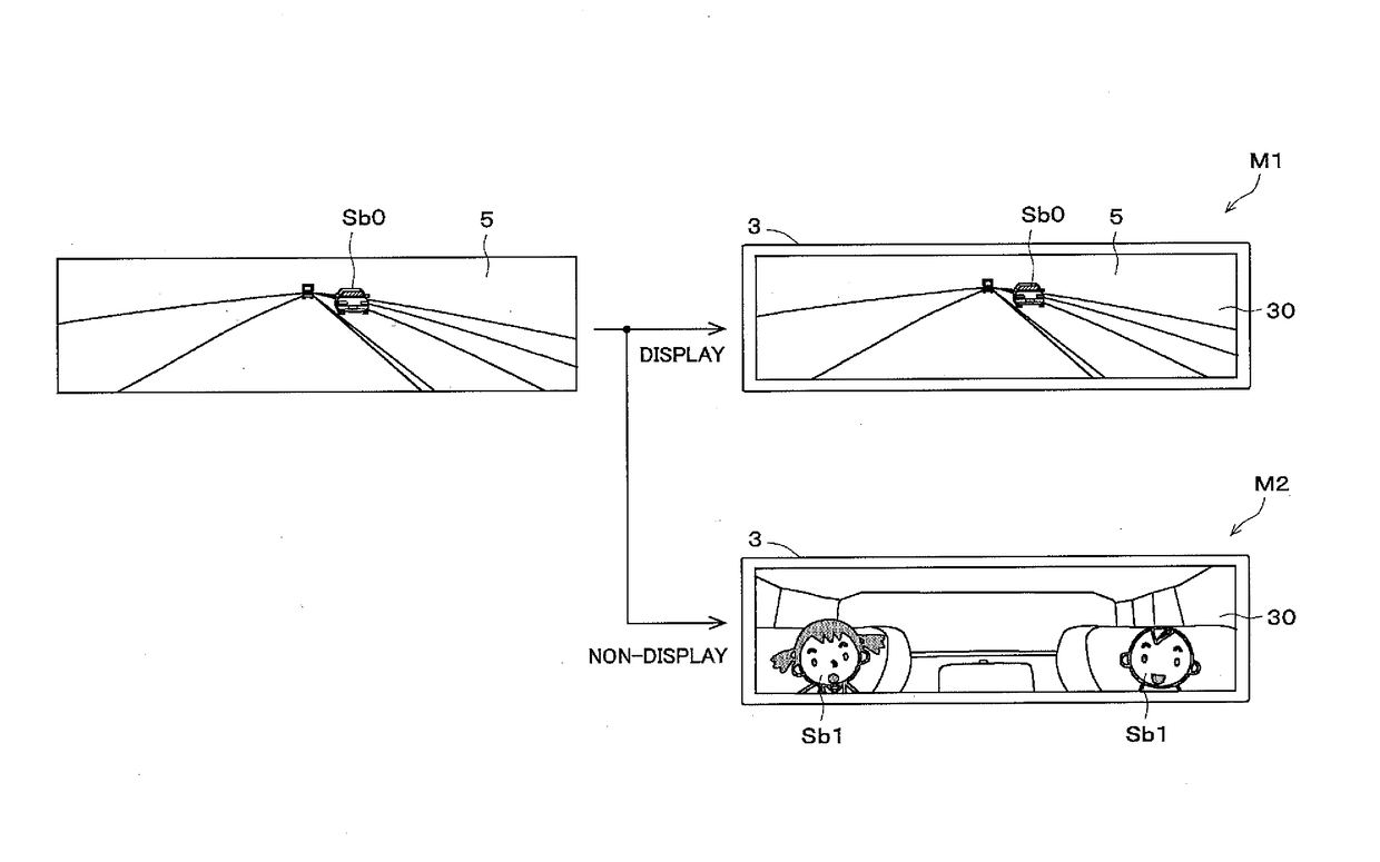
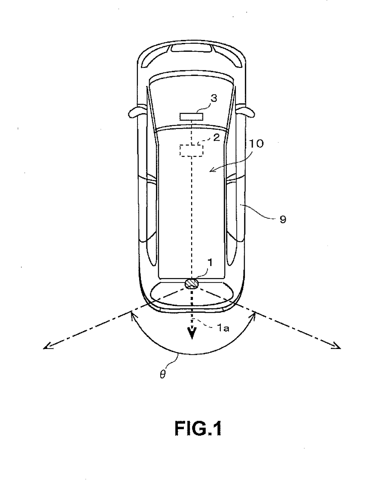
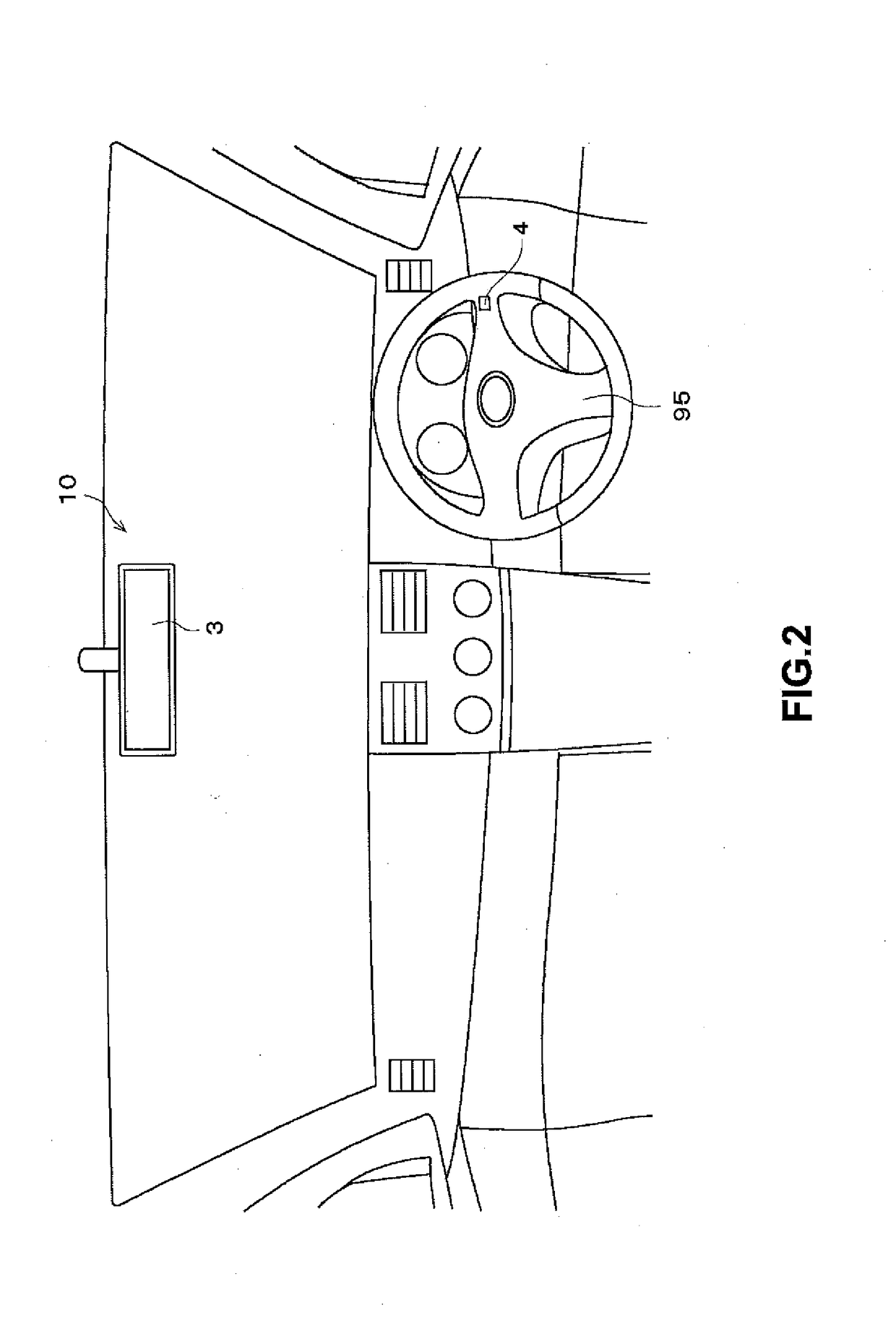
[0027]FIG. 1 illustrates an outline of an image display system 10. As shown in FIG. 1, the image display system 10 is mounted on a vehicle (a car in this embodiment) 9. The image display system 10 includes: a camera 1 that captures images of surroundings of the vehicle 9; a display apparatus 3 that is provided in a cabin of the vehicle 9; and a display control apparatus 2 that entirely controls the image display system 10. The image display system 10 obtains the captured images of the surroundings of the vehicle 9, using the camera 1, and displays the captured images on the display apparatus 3 in the cabin of the vehicle 9.

[0028]The camera 1 includes a lens and an image sensor, and electronically captures the captured images including an image of a subject in the surroundings of the vehicle 9. The camera 1 is mounted in an upper area of a rear end of the vehicle 9, having an optical axis 1a directed rearward in a front-back dire...

second embodiment

2. Second Embodiment

[0066]Next, a second embodiment will be described. A configuration and a process of an image display system 10 in the second embodiment are substantially the same as the configuration and the process of the image display system 10 in the first embodiment. Therefore, a difference from the image display system 10 in the first embodiment will be mainly described below. In the first embodiment, the state determination part 20a determines, based on the speed signal indicative of the speed of the vehicle 9, whether the state of the vehicle 9 is the travelling state or the stopped state. However, in the second embodiment, a state determination part 20a determines, based on a shift signal indicative of a position of a gearshift of a transmission of a vehicle 9, whether a state of the vehicle 9 is the travelling state or the stopped state.

[0067]The process performed by the image display system 10 in the second embodiment is different from the process in the first embodime...

third embodiment

3. Third Embodiment

[0074]Next, a third embodiment will be descried below. A configuration and a process of an image display system 10 in the third embodiment are substantially the same as the configuration and the process of the image display system 10 in the first embodiment. Therefore, a difference from the image display system 10 in the first embodiment will be mainly described below. In the first embodiment, the state determination part 20a determines, only based on the speed signal indicative of the speed of the vehicle 9, whether the state of the vehicle 9 is the travelling state or the stopped state. However, in the third embodiment, a state determination part 20a determines a state of a vehicle 9 based on both a speed signal and a shift signal. Moreover, the state determination part 20a determines the state of the vehicle 9 from amongst three states of the travelling state, the stopped state and a backward-moving state.

[0075]FIG. 9 illustrates a process flow of the image dis...


PUM


Abstract

A display screen of a display apparatus in an image display system includes a one-way mirror on a front side of the display screen. Moreover, an image obtaining part of a display control apparatus obtains a captured image captured by a camera that captures an image of surroundings of a vehicle. The image display system includes, as operation modes, an image display mode that displays the captured image on the display apparatus and a mirror mode that causes the display apparatus to be in a non-display state to cause the display screen of the display apparatus to function as a mirror. A determination part determines a state of the vehicle based on a signal relating to the vehicle and a mode setter sets the operation mode based on the state of the vehicle.

Description

BACKGROUND OF THE INVENTION[0001]Field of the Invention[0002]This invention relates to a technology for displaying an image showing surroundings of a vehicle.[0003]Description of the Background Art[0004]Generally, a driver of a vehicle, such as a car, sees a surrounding area behind the vehicle by looking at an interior rearview mirror provided in a cabin of the vehicle. However, even if the driver uses the interior rearview mirror, there is a case where it is difficult for the driver to see the surrounding area behind the vehicle because driver's view is blocked by luggage and the like in a rear area of the cabin of the vehicle. Moreover, in a case of a truck having a container and the like, there is a case where the interior rearview mirror cannot be used to see the surrounding area behind the vehicle.[0005]Therefore, an image display system has been recently proposed that obtains images of the surrounding area behind the vehicle by capturing the images with a camera, and that caus...

Claims


Application Information

Patent Timeline
Patent Type & Authority Applications(United States)
IPC IPC(8): G02B27/01
CPCG02B27/0101G02B2027/0183G02B2027/0138G02B27/01B60R1/04B60R2001/1253B60R2300/404
Inventor YOSHIMOTO, TAKUMI
Owner FUJITSU GENERAL LTD
Why Eureka
Try Eureka