

Electronic timepiece
a technology of electronic timepieces and hands, applied in the field of electronic timepieces, can solve the problem of limiting the rate of simple rapid shift of hands of such electronic timepieces to a certain level
- Summary
- Abstract
- Description
- Claims
- Application Information
AI Technical Summary
Benefits of technology
Problems solved by technology
Method used
Image

Examples
first embodiment
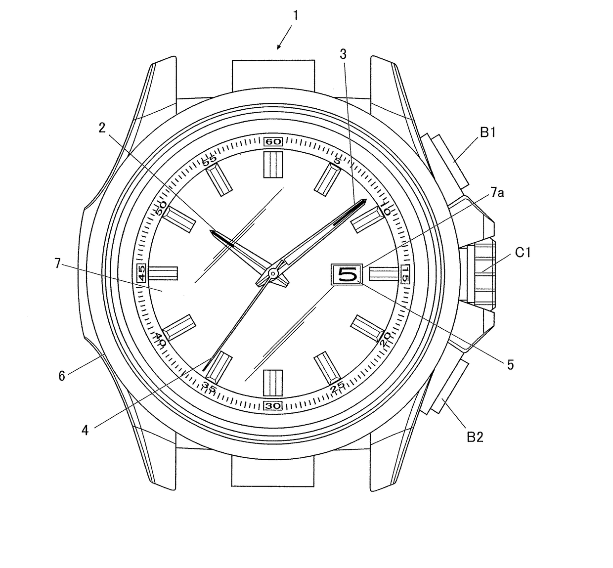
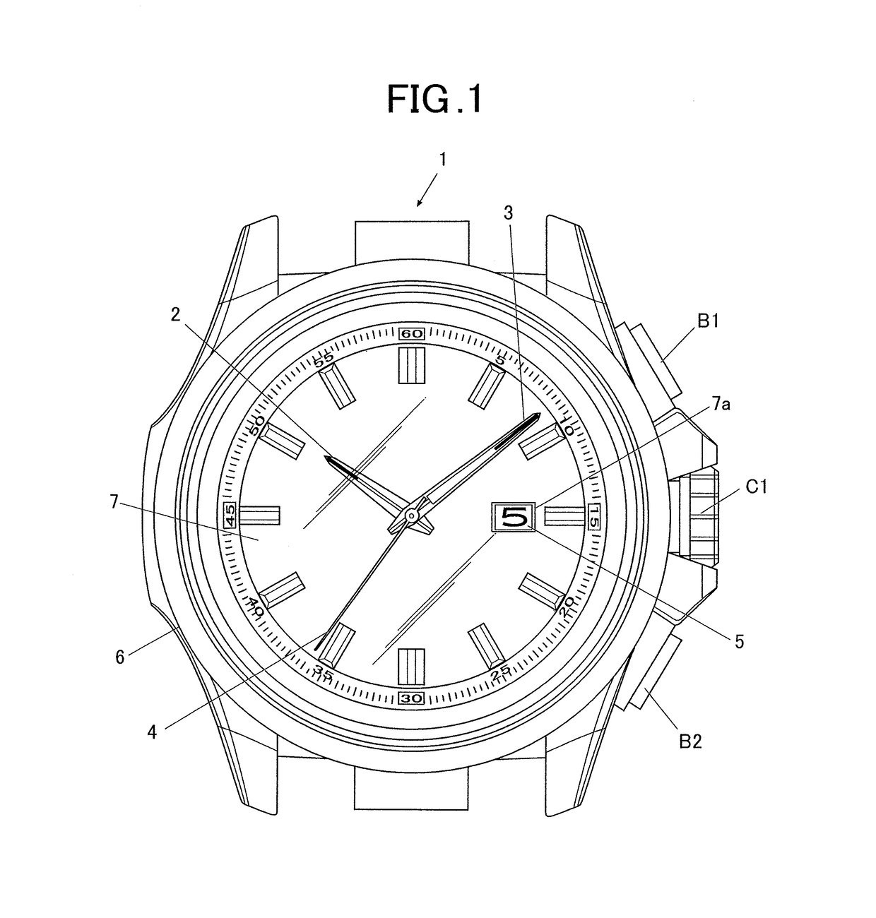
[0042]FIG. 1 is a front view of an analog electronic timepiece 1 according to a first embodiment of the present invention.
[0043]The analog electronic timepiece 1 (electronic timepiece) according to this embodiment can display the date and time with four hands including a rotary disk. The analog electronic timepiece 1 includes a casing 6, a timepiece face 7, an hour hand 2 (secondary hand), a minute hand 3 (primary hand), and a second hand 4. The hour hand 2, the minute hand 3, and the second hand 4 are disposed between the timepiece face 7 and a windproof glass (not shown) covering the front face of the timepiece face 7. A discoid date wheel 5 is disposed parallel to the timepiece face 7 on the rear face of the timepiece face 7. Numerals “1” to “31” representing dates are provided at equal intervals (at every 360 / 31 degrees) in an ascending order on the circumference of the face of the date wheel 5 adjacent to the timepiece face 7. One of the numerals is selectively exposed through ...
second embodiment
[0120]An analog electronic timepiece 1 according to a second embodiment will now be described.
[0121]The configuration of the analog electronic timepiece 1 according the second embodiment is identical to that of the analog electronic timepiece 1 according to the first embodiment Thus, the same reference signs will be used, and the descriptions thereof are omitted.
[0122]FIG. 8 illustrates the shifting of the minute hand 3 of the analog electronic timepiece 1 according to this embodiment during a rapid shift operation.
[0123]The analog electronic timepiece 1 according to this embodiment always bounces in the counterclockwise direction.
[0124]When the hands 2 and 3 reach the set position Pdm at a rapid shift velocity V≧0 (clockwise rapid shift in a predetermined incident direction), the hands 2 and 3 bounce at the set position Pdm in a manner similar to that in the first embodiment and return to the counterclockwise side, as indicated by the thick dotted line in the drawing. When the hand...
third embodiment
[0133]An analog electronic timepiece 1 according to a third embodiment will now be described.
[0134]The configuration of the analog electronic timepiece 1 according the third embodiment is identical to that of the analog electronic timepiece 1 according to the first embodiment. Thus, the same reference signs will be used, and descriptions thereof are omitted.
[0135]FIG. 11 illustrates the shifting of the hour and minute hands of the analog electronic timepiece 1 according to this embodiment during a rapid shift operation.
[0136]In the analog electronic timepiece 1 according to the third embodiment, the rapidly shifted hour and minute hands reach the set position Pdm and are damped about the center or set position Pdm, instead of a bouncing operation. In this process the coefficient of restitution r of the damping setting 472 corresponds to the damping rate of the initial velocity V0 per cycle, which is determined by comparing the initial velocity V0 with the initial velocity V0 of the ...
PUM
 Abstract
Description
Claims
Application Information