Method for operating intrinsically safe battery cells

a battery cell and safe technology, applied in secondary cell servicing/maintenance, instruments, electrochemical generators, etc., can solve the problems of battery cell plating and breakdown risk at low temperatures, and achieve efficient service, efficient monitoring, and cell efficiency and operation safety.

Active Publication Date: 2017-03-23
ROBERT BOSCH GMBH
View PDF2 Cites 1 Cited by
  • Summary
  • Abstract
  • Description
  • Claims
  • Application Information

AI Technical Summary

Benefits of technology

[0012]The advantage of the invention is that an intrinsically safe battery cell, which is also referred to below as battery cell and is operated in accordance with the method according to the invention, can now be operated in a plurality of operating modes. Within the various operating modes, the battery cell is subjected to examinations of different intensity and thus efficiently serviced. In the case in which an inventive intrinsically safe battery cell has been subjected to the particular danger of plating due to charging at low temperatures, the discharge curve is determined during the subsequent discharging process.
[0013]According to the invention, this discharging process or respectively the effort for this discharging process must not be performed / made for each cycle but can be performed / made in an efficient manner only in the case where danger might occur to the cell.
[0014]In a further step, the discharge curve is examined after the presence of plating criteria. If no plating criteria are present, the battery cell continues to be operated in a normal mode. The parameters of the battery cell are typically monitored even in this normal mode; however, a discharge curve does not have to be determined.
[0015]Should, on the other hand, the presence of the plating criteria be established, the cell is then operated henceforth in a monitoring mode, in which the capacity of the battery cell is monitored. The advantage of the invention is that the monitoring is efficiently carried out only in the case in which a concrete reason is given. The monitoring of the capacity of the battery cell has the advantage that changes in the capacity can be determined which suggest the efficiency and operating safety of the cell and if need be allow for further measures to be taken. The method according to the invention thus contributes advantageously to an efficient increase in the operating safety in the sense of an intrinsically safe battery cell.
[0016]The method according to the invention advantageously comprises a further step in which, in the event that a rapid loss in capacity of the intrinsically safe battery cell is determined, a change is made to an operation in a safety mode, in which the intrinsically safe battery cell is deactivated. In so doing, the intrinsically safe battery cell is, for example, separated from a circuit arrangement connected to the intrinsically safe battery cell via an internal switching device. If the intrinsically safe battery cell is operated in a series circuit, a bypass is thus formed by the switching device.
[0017]In this case, a rapid loss of capacity is to be understood as a significant drop in the capacity of the battery cell from one cycle to the next or within a few cycles. The capacity of the battery cell normally drops by 0.1% to 1% with the first 50 to 100 cycles. This corresponds to an average gradient between 0.01% and 0.2% per cycle. If this gradient climbs by 10 to 100 times within one cycle or within a few cycles, for example ten, i.e. to values of 0.1% to 1%, a rapid loss in capacity is then present.

Problems solved by technology

The charging of a battery cell, in particular a lithium ion cell, at low temperatures entails the risk of plating as well of the breakdown of the battery cell.

Method used


Image

  • Method for operating intrinsically safe battery cells
  • Method for operating intrinsically safe battery cells
  • Method for operating intrinsically safe battery cells

Examples


Embodiment Construction

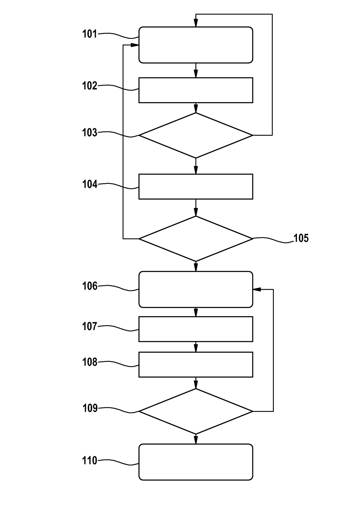
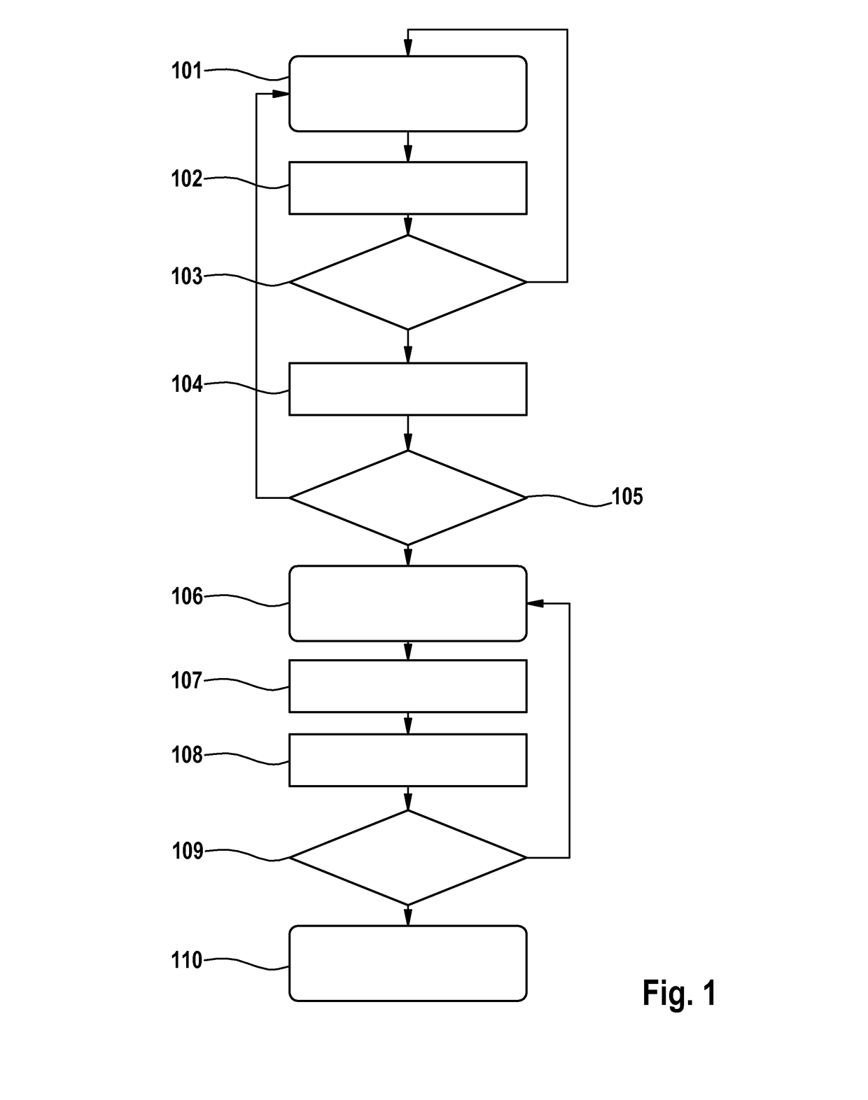
[0035]FIG. 1 shows an exemplary embodiment of the method in the form of a flow diagram. In a normal operating mode, which is characterized in FIG. 1 by step 101, an intrinsically safe battery cell 1, which is described below in detail in relation to FIG. 7, is charged in step 102. In step 103, a check is made whether the intrinsically safe battery cell 1 was charged at a low temperature. If the intrinsically safe battery cell has been charged, for example, at room temperature a typical discharging process, which is not shown here, takes place and the method is continued at step 101 so that the intrinsically safe battery cell 1 continues to be operated in the normal operating mode and is recharged in a following cycle in step 102. If, however, the intrinsically safe battery cell 1 has been charged at a low temperature, i.e. at 0° C. or below, the discharge curve is determined during the succeeding discharging process and is analyzed in step 105 in regard to the presence of plating cr...


PUM

PropertyMeasurementUnit
temperatureaaaaaaaaaa
discharge voltageaaaaaaaaaa

Abstract

The invention relates to a method for operating intrinsically safe battery cells after charging of an intrinsically safe battery cell at a low temperature. In accordance with the invention, provision is made here for the determination of the discharge curve of the battery cell to then be performed, for the discharge curve of the battery cell to be analysed in respect of the presence of plating criteria and for a change to operation in a monitoring mode to be made if at least one plating criterion is present, wherein the capacity of the intrinsically safe battery cell is monitored in the monitoring mode. The invention furthermore relates to an intrinsically safe battery cell which is designed for implementing the method.

Description

BACKGROUND OF THE INVENTION[0001]The invention relates to a method for operating intrinsically safe battery cells after charging of an intrinsically safe battery cell at a low temperature.[0002]Battery cells are used in numerous ways in energy storage systems for stationary as well as mobile applications, such as, for example, in emergency power systems or in the automotive industry for electric and hybrid vehicles. In these applications, a plurality of battery cells are connected to one another in series and / or also in parallel to form battery modules and batteries.[0003]Due to manufacturing tolerances and or age related losses of capacity, the capacity of the battery cells connected together to form batteries is not always exactly the same. Charging and discharging of the battery cells, however, typically occurs jointly in a composite, whereby there is, for example, the danger of overcharging or deep discharging individual battery cells. There is consequently the danger of overhea...

Claims


Application Information

Patent Timeline
Patent Type & Authority Applications(United States)
IPC IPC(8): H01M10/48G01R31/36H01M10/42
CPCH01M10/48G01R31/3606H01M10/4257H01M10/052H01M10/0525H01M10/425H01M10/484H02J7/0024G01R31/374G01R31/382H02J7/0048Y02T10/70Y02E60/10G01R31/385
Inventor HORE, SARMIMALAPARTES, HANS
Owner ROBERT BOSCH GMBH
Why Eureka
Try Eureka