Exercise Machine Support System

a support system and exercise machine technology, applied in the field of support systems for exercise machines, can solve the problems of increasing the chance that an exerciser will trip, fall, injury, etc., and the overall length and width of the perimeter structure, and the pilates apparatus and structure become physically large and cumbersom

Active Publication Date: 2017-03-30
LAGREE TECH INC
View PDF3 Cites 64 Cited by
  • Summary
  • Abstract
  • Description
  • Claims
  • Application Information

AI Technical Summary

Problems solved by technology

Moving the slidable carriage along the rails in a direction opposite the end of the apparatus to which the spring resistance is attached creates a workload against which therapeutic or fitness exercises can be safely and beneficially performed.
One major deficiency related to the design of currently available apparatuses is that the rails, slidable carriage and bias members are located within the generally rectangular perimeter structure, requiring exercisers to step over the perimeter structure in order to mount the apparatus.
Stepping over a perimeter structure to mount or dismount the apparatus is unnatural and awkward, and increases the chances that an exerciser will trip, fall, and become injured during mounting or dismounting the apparatus.
Another major deficiency of currently available exercise machines is that the overall length and width of the perimeter structure must be sufficiently large enough to accommodate the installation of the parallel rails, spring biasing means and slidable carriage within the major dimensions of the perimeter structure.
The resulting Pilates apparatus and structure therefore becomes physically large and cumbersome.
Therefore, reducing the total number of Pilates apparatuses that can be installed within a studio of a given size directly correlates to reduced revenue opportu

Method used


Image

  • Exercise Machine Support System
  • Exercise Machine Support System
  • Exercise Machine Support System

Examples


Embodiment Construction

A. Overview

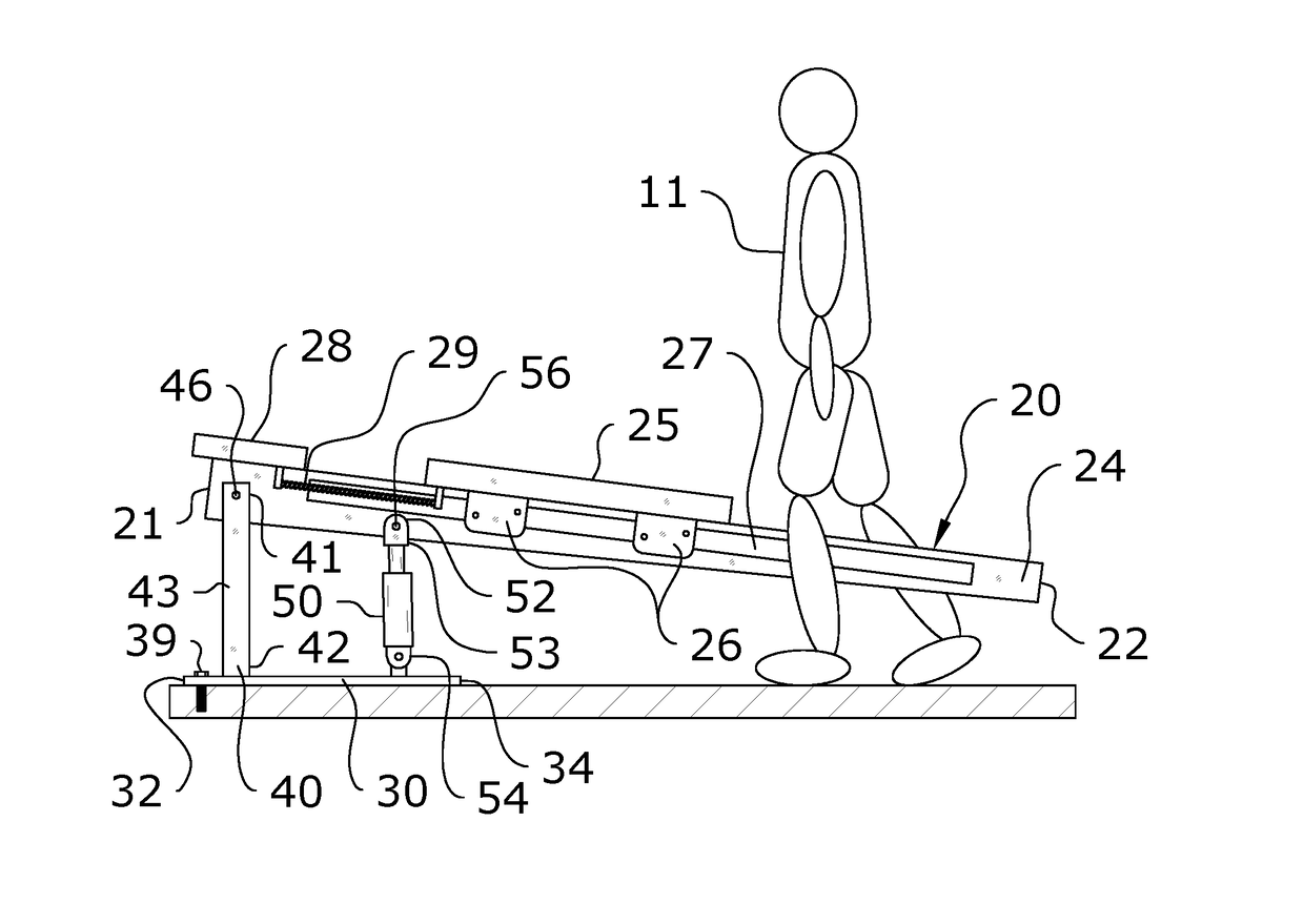
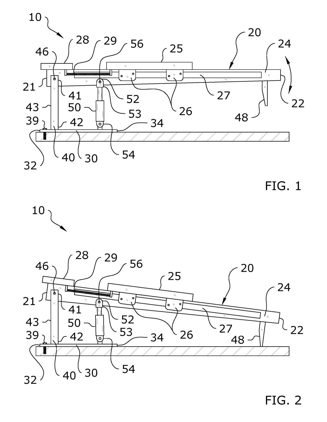
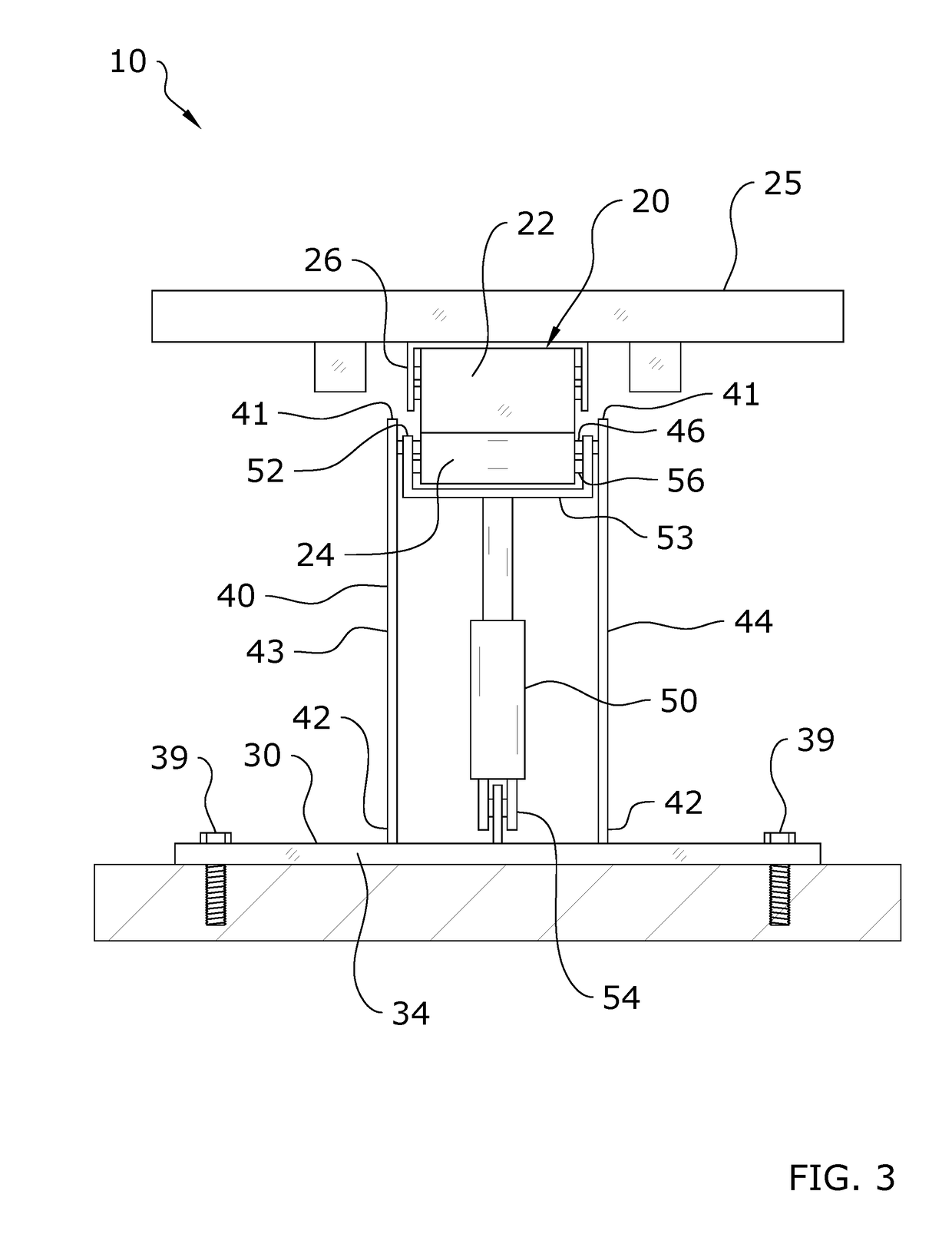
[0047]Turning now descriptively to the drawings, in which similar reference characters denote similar elements throughout the several views, FIGS. 1 through 25 illustrate a exercise machine support system 10, which comprises a cantilevered exercise machine 20 which is adapted to have a variable angle of incline or decline with respect to a horizontal ground surface. The exercise machine 20 will generally include a base 20 and a support 40 which extends between the base 20 and the exercise machine 20. The upper end 42 of the support 40 is connected to the exercise machine 20 by a first pivot 46 such that the exercise machine 20 pivots about the support 40. An adjustment device 50 may be utilized to pivot the exercise machine 20 and thus adjust its angle of incline. Various types of adjustment devices 50 are disclosed, including an actuator, ratchet-and-pawl, gears 70, 72, and cam 74.

[0048]The present invention is a new and novel exercise machine 20 that reduces the overall...


PUM


Abstract

An exercise machine support system for providing increased versatility including inclination or declination of an exercise surface, a reduction in the overall length and width of the exercise machine, and an enhanced user interface which reduces the risk of injury. The exercise machine support system generally includes a cantilevered exercise machine which is adapted to have a variable angle of incline or decline with respect to a horizontal ground surface. The exercise machine will generally include a base and a support which extends between the base and the exercise machine. The upper end of the support is connected to the exercise machine by a first pivot such that the exercise machine pivots about the support. An adjustment device may be utilized to pivot the exercise machine and thus adjust its angle of incline. Various types of adjustment devices are disclosed, including an actuator, ratchet-and-pawl, gears, and cam.

Description

CROSS REFERENCE TO RELATED APPLICATIONS[0001]The present application is a continuation of U.S. application Ser. No. 14 / 742,106 filed on Jun. 17, 2015 (Docket No. LAGR-041), which is a continuation-in-part of U.S. application Ser. No. 14 / 725,908 filed May 29, 2015 now issued as U.S. Pat. No. 9,370,679 (Docket No. (LAGR-031), which is a continuation-in-part of U.S. application Ser. No. 14 / 468,958 filed Aug. 26, 2014 now issued as U.S. Pat. No. 9,211,440 (Docket No. LAGR-036). U.S. application Ser. Nos. 14 / 725,908 and 14 / 468,958 both claim priority to U.S. Provisional Application No. 61 / 869,904 filed Aug. 26, 2013 (Docket No. LAGR-008). U.S. application Ser. No. 14 / 742,106 claims priority to U.S. Provisional Application No. 62 / 013,028 filed Jun. 17, 2014 (Docket No. LAGR-020) and U.S. Provisional Application No. 62 / 090,077 filed Dec. 10, 2014 (Docket No. LAGR-040). Each of the aforementioned patent applications, and any applications related thereto, is herein incorporated by reference ...

Claims


Application Information

Patent Timeline
IPC IPC(8): A63B21/00A63B21/005A63B21/04A63B21/008A63B21/02
CPCA63B21/00069A63B21/008A63B21/0085A63B21/0058A63B21/0428A63B21/4035A63B21/4047A63B21/023A63B21/00061A63B21/00065A63B21/0083A63B21/0087A63B21/0442A63B21/0552A63B21/068A63B21/4043A63B22/0012A63B22/0023A63B22/0046A63B22/0087A63B22/0089A63B22/203A63B22/205A63B23/0211A63B23/03541A63B23/047A63B23/1209A63B24/0087A63B2023/003A63B2024/0093A63B2208/0204A63B2208/0214A63B2208/0219A63B2208/0242A63B2225/50A63B24/0084
Inventor LAGREE, SEBASTIEN ANTHONY LOUIS
Owner LAGREE TECH INC
Why Eureka
Try Eureka