Device for Vaporization of Phyto Material

a technology of phytomaterials and vaporizers, applied in the direction of inhalators, ohmic-resistance heating, other medical devices, etc., can solve the problem of user's lips being slashed

Inactive Publication Date: 2017-04-06
GSEH HOLISTIC INC
View PDF4 Cites 48 Cited by
  • Summary
  • Abstract
  • Description
  • Claims
  • Application Information

AI Technical Summary

Benefits of technology

[0007]In accordance with the embodiments of the invention there is provided: a herbal vaporization device comprising: a first housing comprising a first end and a second end upstream of the first end and a fluid pathway starting from a downstream ambient air input port disposed proximate the first end and propagating to the second end and terminating at an inhalation aperture proximate the second end, the fluid pathway comprising: a heating chamber fluidly coupled with the downstream ambient air input port in fluid communication with an outside environment through the ambient air input port and fluidly coupled with an upstream vapor and air cooling member, wherein the inhalation aperture is disposed upstream of the vapor and air cooling member, the heating chamber for in a first mode of operation for receiving of phyto material therein and for in a second mode of operation for heating of the phyto material at a predetermined temperature and for heating of the phyto material for at least partial vaporization thereof, the heating chamber comprising: a heating chamber first portion and a heating chamber second portion, wherein the heating chamber first and second portions in the second mode of operation have the first portion and the second portion proximate each other and form an approximately enclosed fluid pathway and where in the first mode of operation form an other than approximately enclosed fluid pathway and allow for the receiving of phyto material therein; the heating chamber first portion comprising an airflow restricting member and a vapor capturing chamber disposed upstream thereof; the heating chamber second portion comprising a low thermal inertia conductive heating element having a control circuit first electrical coupling; a first battery at least partially disposed within the first housing; a first control circuit coupled with the first battery and the control circuit first electrical coupling, the first control circuit for controlling the flow of electrical current from the first battery to the low thermal inertia conductive heating element; a first battery first recharging port coupled with the first control circuit; a switch coupled with the first control circuit for providing a control signal to the first control circuit for affecting the flow of electrical current from the first battery to the low thermal inertia conductive heating element, wherein in use, in the second mode of operation upon activating the switch, electrical current is applied to the control circuit first electrical coupling and the low thermal inertia conductive heating element is heated to the predetermined temperature and the phyto material is heated and vapor emitted therefrom propagates through apertures of a predetermined size formed in the airflow restricting member and into the vapor capturing chamber for further propagation into the vapor and air cooling member for inhalation from the inhalation aperture, wherein further in use, the phyto material in the second mode of operation is compressed between the airflow restricting member and the low thermal inertia conductive heating element.
[0008]In accordance with the embodiments of the invention there is provided a herbal vaporization device comprising: a first housing comprising a first end and a second end upstream of the first end and a fluid pathway s

Problems solved by technology

In some of the prior art vaporization devices the vapor released from the materials are quite hot, around 230 degrees Celsius and may cause discomfort when inhaled by a user, which is typically a result of the close

Method used


Image

  • Device for Vaporization of Phyto Material
  • Device for Vaporization of Phyto Material
  • Device for Vaporization of Phyto Material

Examples


Embodiment Construction

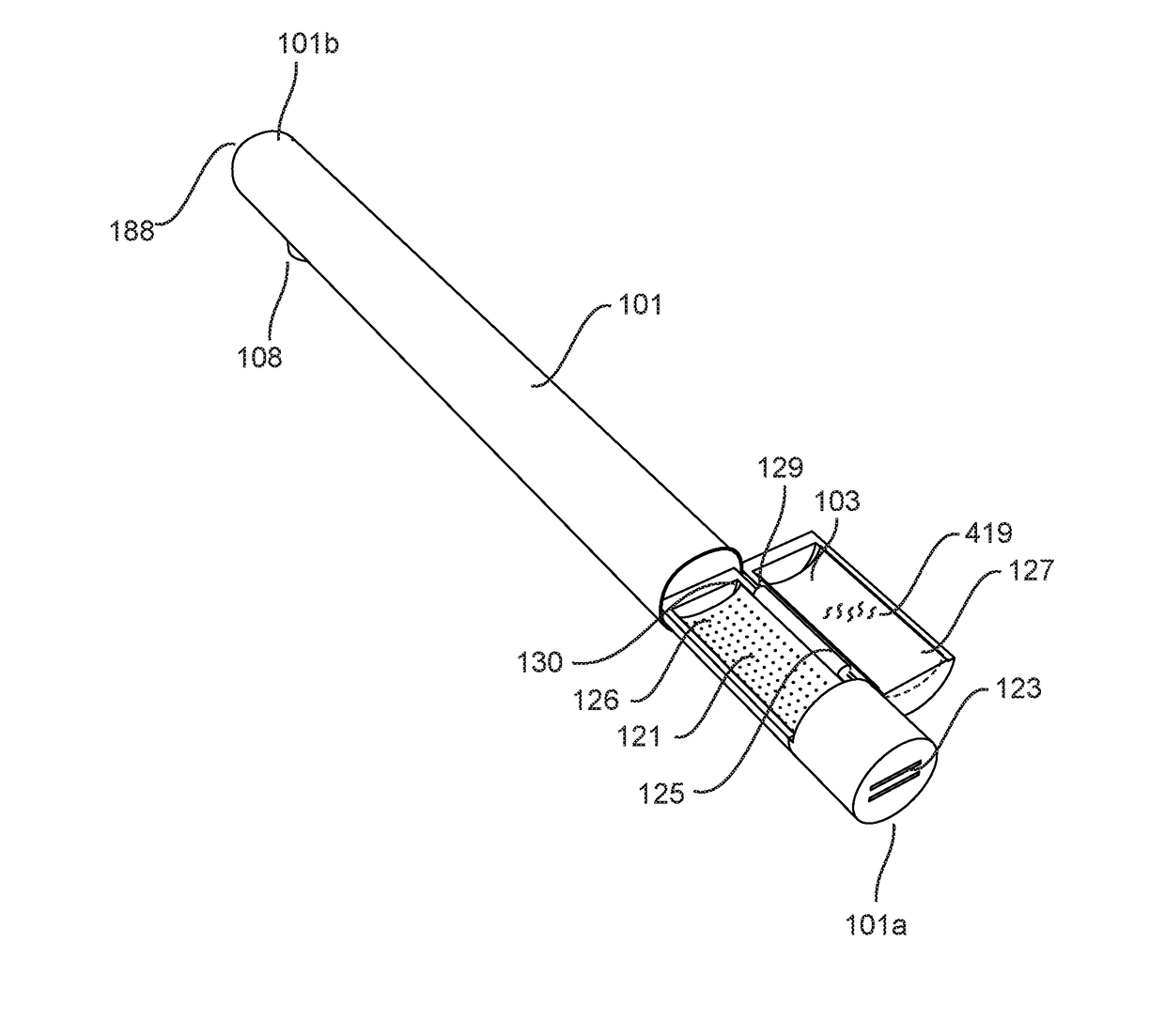
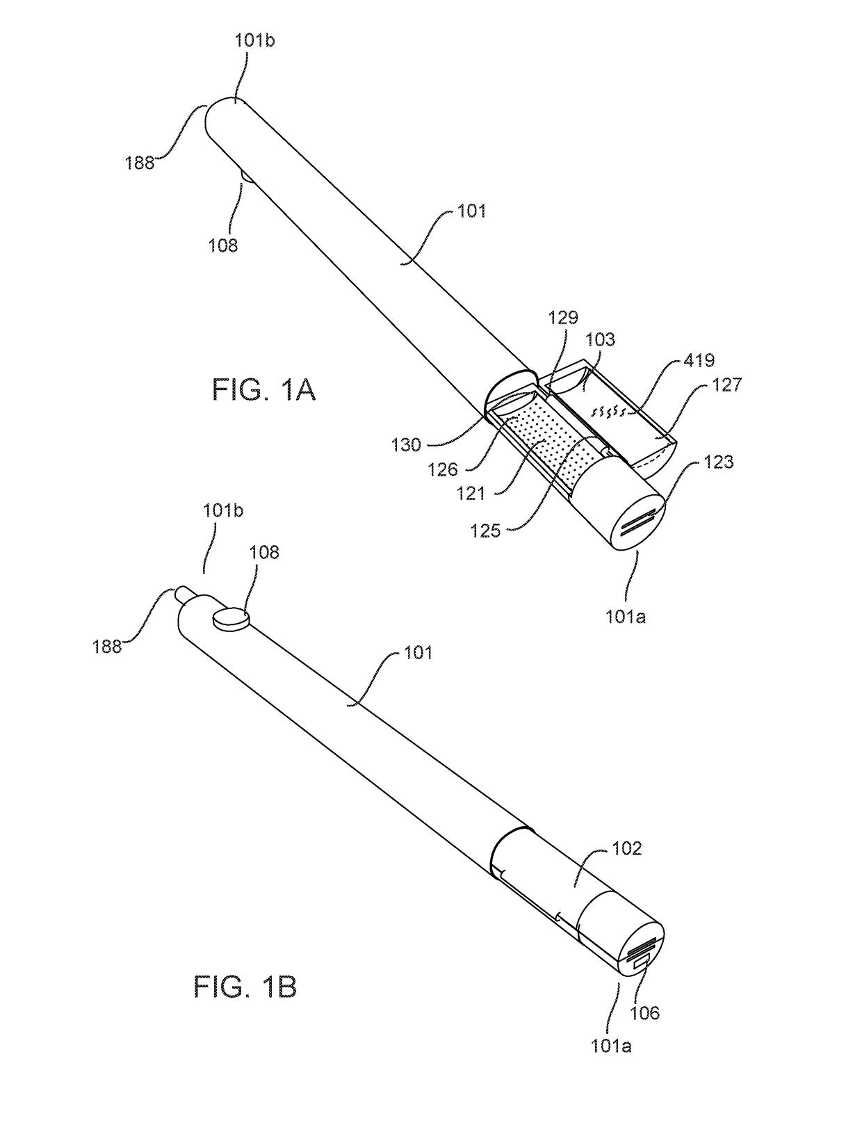
[0013]For the purposes of this detailed description, the term loose leaf herbal material is categorized as phyto material 419 and includes phyto material extract, where the phyto material extract is derived from the phyto material 419 or from the loose leaf herbal material.

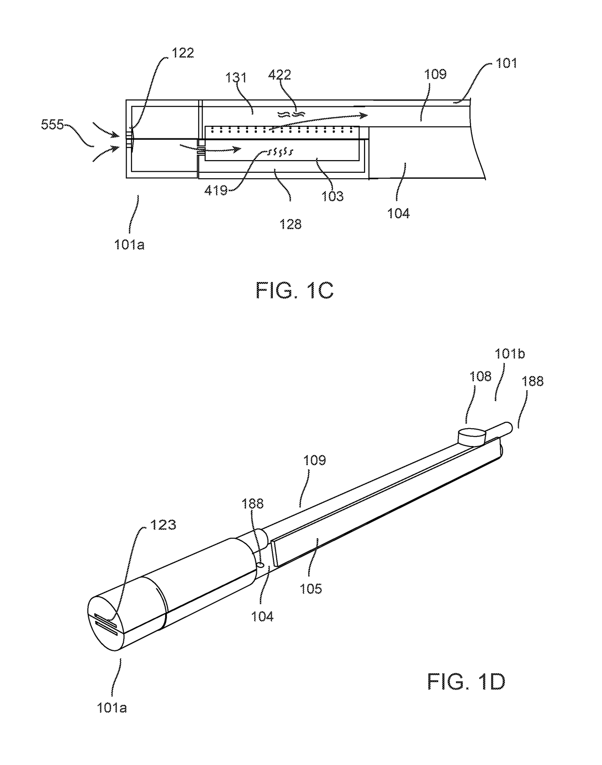
[0014]FIG. 1A illustrates a herbal vaporization device (HVD) 100 in accordance with a first embodiment of the invention. The HVD is formed from a first housing 101 having a first end 101a and a second end 101b upstream of the first end 101a and a fluid pathway 109 starting from a downstream ambient air input port 123 disposed proximate the first end and propagating to the second end and terminating at an inhalation aperture 188 proximate the second end 101b.

[0015]The fluid pathway 109 includes a heating chamber 102 fluidly coupled with the downstream ambient air input port 123 in fluid communication with an outside environment through the ambient air input port 123 and fluidly coupled with an upstream vapor and a...


PUM


Abstract

A novel Aromatherapy Vaporization Device is disclosed having a heating chamber first portion with an airflow restricting member and a vapor capturing chamber disposed upstream thereof. A heating chamber second portion has a low thermal inertia conductive heating element having a control circuit first electrical coupling. Phyto material is inserted between the first and second heating chamber portions for heating thereof to a predetermined temperature. A hinge is disposed between the heating chamber first portion and the heating chamber second portion for facilitating loading of phyto material into the heating chamber.

Description

CROSS REFERENCE TO RELATED APPLICATION[0001]This application benefits from the priority of U.S. Provisional Applications 62 / 236,162 filed on Oct. 2, 2015, which is incorporated herein by reference.TECHNICAL FIELD OF THE INVENTION[0002]The technical field relates to a device for vaporization of phyto materials and more specifically to a device for use in aromatherapy vaporization.BACKGROUND OF THE INVENTION[0003]Aromatherapy generally uses essential oils, which are extracted from phyto materials, such as leaves of plants, for therapeutic benefits. These essential oils are either massaged into the skin or can be inhaled. In some cases the phyto materials are heated in order to released the essential oils therefrom. By heating these phyto materials at predetermined temperatures, essential oils and extracts are boiled off, depending upon the temperature at which these phyto materials are heated, a vapor, which is a faintly visible suspension of fine particles of matter in the air or aer...

Claims


Application Information

Patent Timeline
IPC IPC(8): A61M11/04A61M15/06H05B1/02A61M15/00A24F40/20A24F40/46A24F40/485A24F40/50
CPCA61M11/042A61M15/0021A61M15/06H05B2203/021A61M2205/8206A61M2205/3368A61M2205/3606H05B1/0244A61M2205/3653H05B1/0227A24F40/46A24F40/50A24F40/485A24F40/20
Inventor TRZECIESKI, MICHAEL
Owner GSEH HOLISTIC INC
Why Eureka
Try Eureka