Sauna with phototherapy lighting

a sauna and phototherapy technology, applied in the field of saunas with phototherapy lighting, can solve the problems of user mobility, user's inability to receive no one has yet addressed the need or found a way to provide full body phototherapy and heat therapy, etc., to achieve the effect of simple and quick assembly and storage, easy attachment with minimal tools, and added stability of the uni

Inactive Publication Date: 2006-09-19
BARGHELAME SI
View PDF9 Cites 18 Cited by
  • Summary
  • Abstract
  • Description
  • Claims
  • Application Information

AI Technical Summary

Benefits of technology

[0017]For simplicity and quickness of assembly and storage, the two side panels are hinged to the back panel and can be folded flat. The floor, bench, the light box (describe below) and front panel are separate and attach easily with minimal tools through special clasp or clamp closures already pre-attached to the pieces. The side and back wall contain preassembled slots to slide the bench into.
[0018]The base is notched around the exterior edges for the sides, front and to fit into before being clamped down, for added stability of the unit. The top of the enclosure is comprised of a box containing a plurality of full spectrum lights that rests on the sidewalls and the back wall. The enclosure can include air vents and in one embodiment of the invention there is an air vent under the bench and another air vent near the top of the enclosure.

Problems solved by technology

Until this point, no one has yet addressed the need or found a way to provide full body phototherapy and heat therapy in a comfortable, pleasant and affordable manner.
The user will not receive the benefits of full body light therapy.
The hood and bed apparatus limit the user's mobility, makes him unaware and not in control of his surroundings, deprives him of full body light therapy and makes him unable to do other activities such as reading.
This type of therapy could be claustrophobic and limiting to the extent that the user would not be very eager to employ it.

Method used


Image

  • Sauna with phototherapy lighting
  • Sauna with phototherapy lighting
  • Sauna with phototherapy lighting

Examples


Embodiment Construction

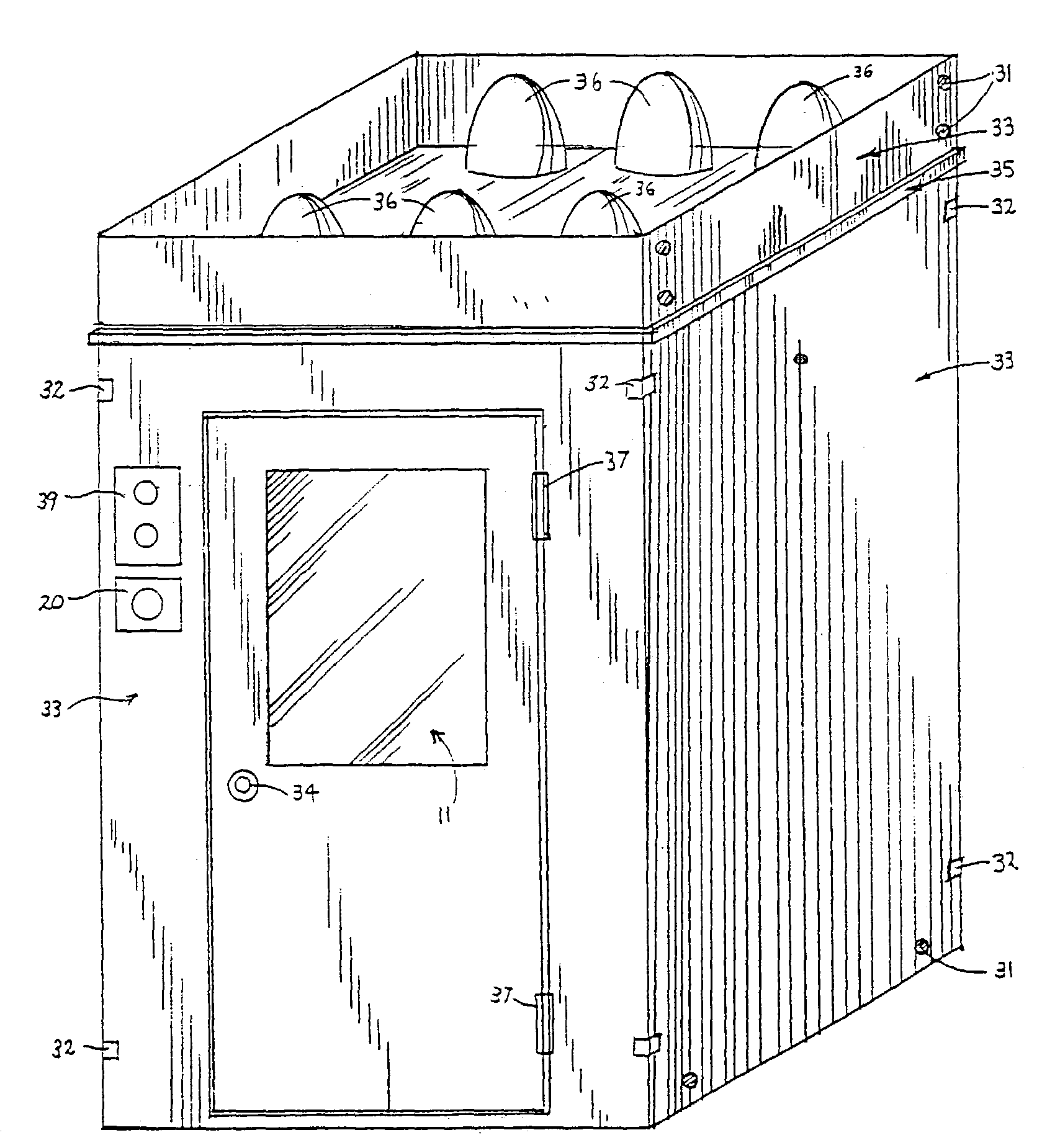
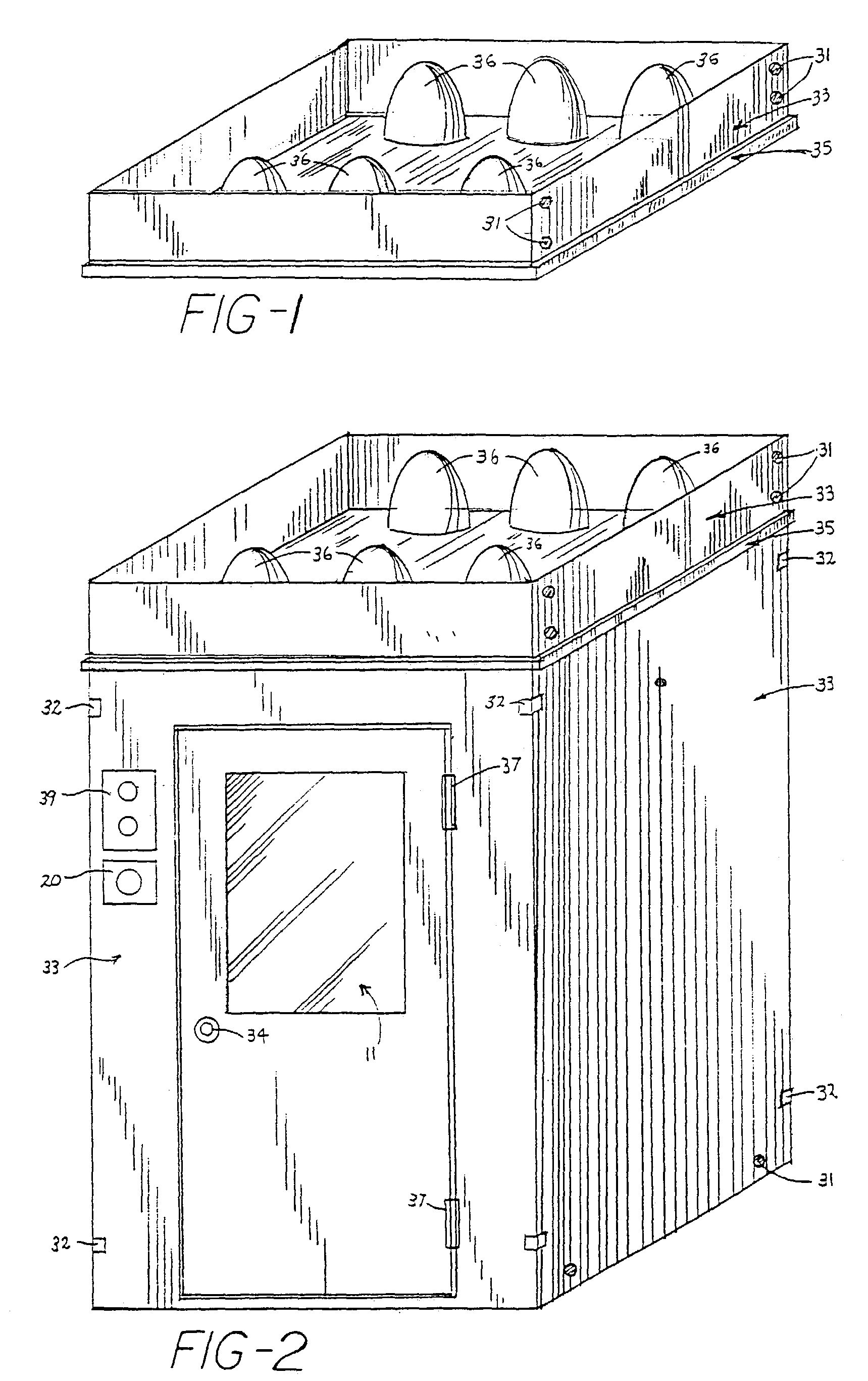
[0037]Turning now to the drawings, the invention will be described in preferred embodiments by reference to the numerals of the drawing figures wherein like numbers indicate like parts. One preferred embodiment of this invention is illustrated in FIG. 1 and FIG. 6, the exterior surface 33 and the interior surface 18 of the sauna are constructed of wood, preferable cedar. The door 38 contains a window 11 and connection hinges 37 and a door handle 34 with a magnetic closure.

[0038]The sides of the sauna are connected by pre-attached clamps 32 and screw assemblies 31. The top of the sauna, consisting of the phototherapy light box contains a wood strip 35 at its base, which overlaps the top of the unit and is held on by gravity. The interior bench 27 is held up by its connection to the back wall and the vertical panel 26. FIG. 2 and FIG. 6 also show the exterior placement for the control panel 39.

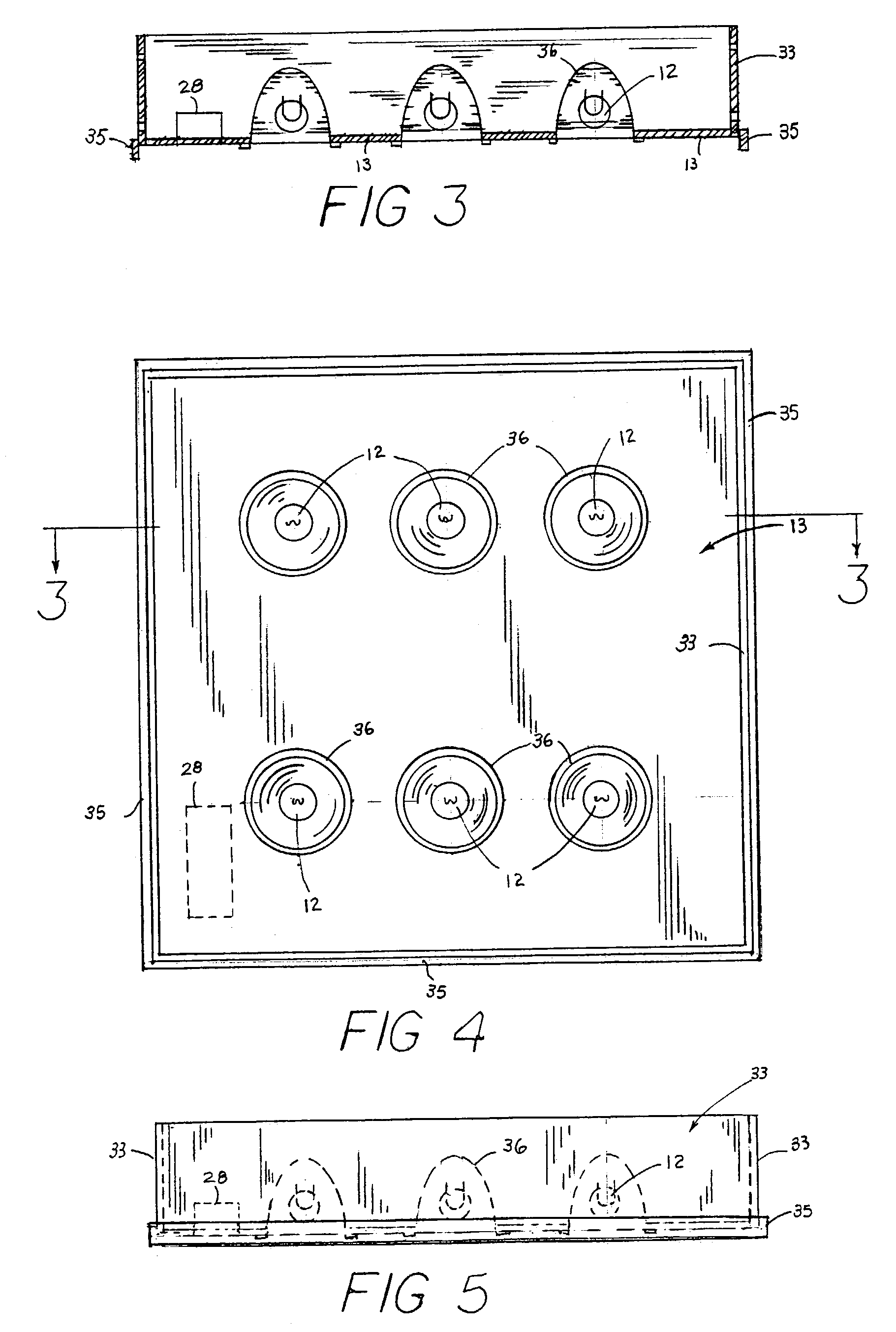
[0039]FIGS. 3, 4, and 5 show the physical structure of the phototherapy light box, which fas...


PUM


Abstract

A radiant, infrared heat sauna with full spectrum, Neodymium or similar lighting. The sauna is portable and can be plugged in to run on standard household current. Radiant heating elements in the walls of the sauna emit infrared rays directly into a person's body, creating penetrating heat thus producing sweat and an overall warming sensation, as well as the provided overhead, adjustable full spectrum lighting which creates a sensation of sunlight on the body. At least one embodiment of the invention includes full spectrum lighting on the walls of the sauna. Embodiments of the invention can also include sound systems, video systems, and aromatherapy devices. The combination of the infrared heating and the full spectrum lighting comes close to recreating the feeling of warmth and well being of enjoying time in the sun, without the harmful UV rays.

Description

CROSS REFERENCE TO RELATED APPLICATION[0001]This application is a continuation of U.S. Utility patent application Ser. No. 09 / 684,685, entitled “Sauna with Phototherapy Lighting, filed Oct. 7, 2000 now abandoned, which claims benefit of Provisional Patent Application No. 60 / 158,593, filed Oct. 7, 1999, entitled “SUN BOX SAUNA AND LIGHT FIXTURE”.FIELD OF INVENTION[0002]The current invention relates to the field of phototherapy lighting and saunas. Specifically, the current invention discloses phototherapy lighting located within a portable sauna, where such sauna and phototherapy lighting combination provides a therapeutic and aesthetic experience that approximates the rays of natural sunlight.BACKGROUND OF THE INVENTION[0003]Saunas have been manufactured and sold on the market for many years. Saunas can employ a variety of heat sources, all with the object of warming a person's body in order to create sweat. The sweating process has several health benefits such as increasing the hea...

Claims


Application Information

Patent Timeline
Patent Type & Authority Patents(United States)
IPC IPC(8): A61N5/06A61H33/06
CPCA61H33/06A61H2201/10A61N2005/0661A61N2/00A61N2005/0659A61H2201/102
Inventor BARGHELAME, SI
Owner BARGHELAME SI
Why Eureka
Try Eureka