
Method and apparatus for mouse positioning device based on infrared light sources and detectors

a positioning device and infrared light technology, applied in the field of pointer positioning devices, can solve the problems of poor user dexterity, low reliability, wear and tear during use,

Inactive Publication Date: 2001-12-25
LENOVO (SINGAPORE) PTE LTD
View PDF13 Cites 140 Cited by
  • Summary
  • Abstract
  • Description
  • Claims
  • Application Information

AI Technical Summary

Benefits of technology

This new pointing device is superior to existing devices because it is independent of touch sensitivity and is more robust. This new pointing device is superior in terms of wear and tear on the touch surface and insensitivity to user's finger condition. Existing touch-pad devices are based on true touch. The touch surface has a sensor beneath it, and is subject to wear. However, in the present invention, the surface on which the finger is moved has no sensors. It just provides a flat surface for supporting the finger or finger operated object during its motion.
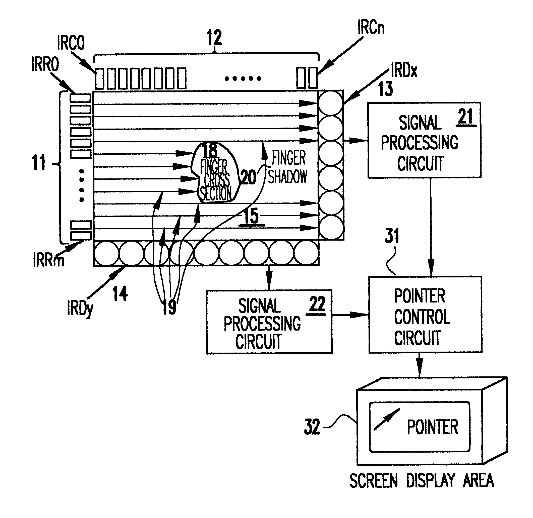
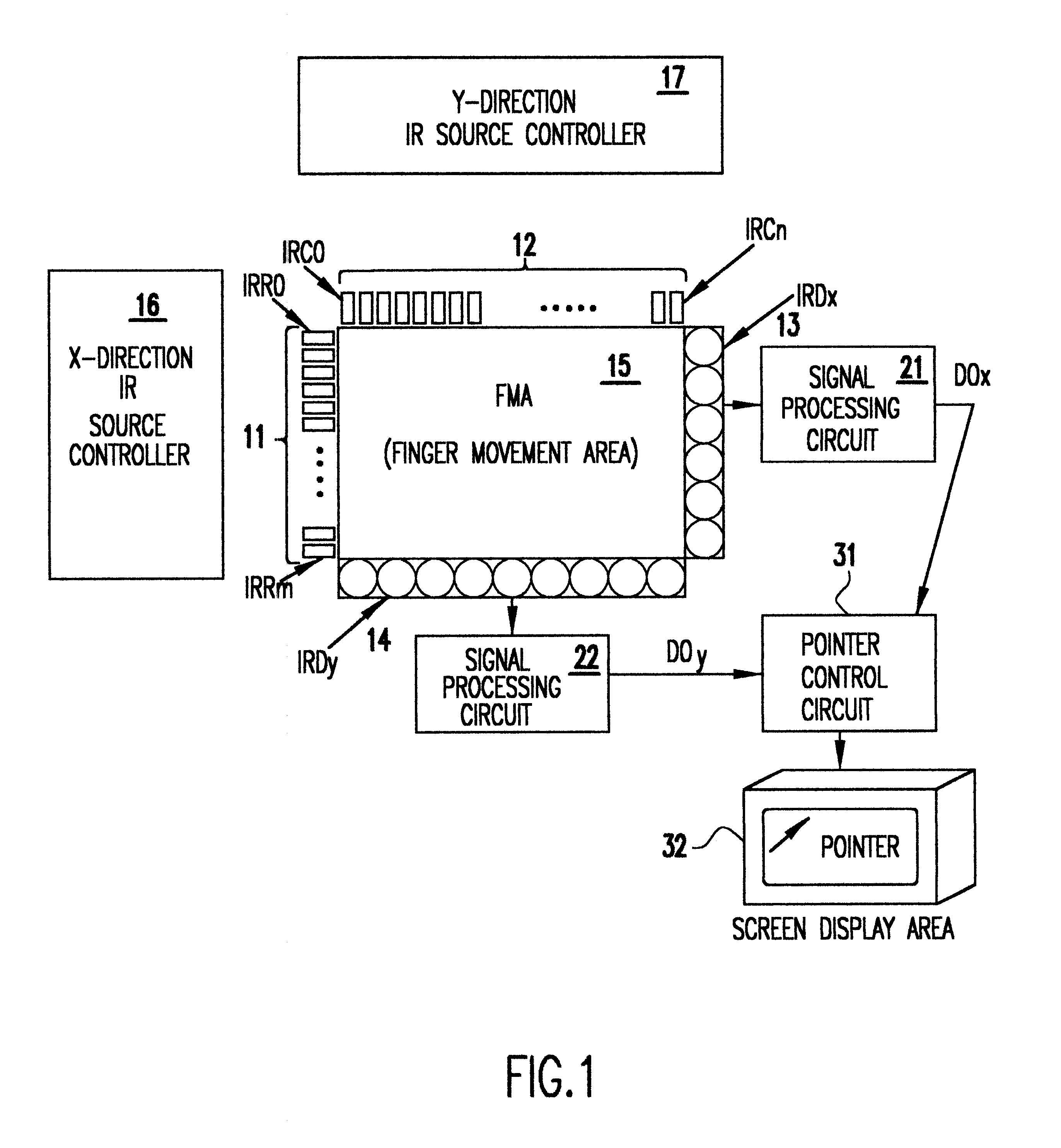
According to a preferred embodiment of the invention, the pointing device comprises an x-direction IR source controller and a y-direction IR source controller and a plurality of x-direction collimated IR light sources and a plurality of y-direction collimated IR light sources. The x and y-direction IR source controllers respectively alternately and sequentially activate the IR light sources in each direction. A plurality of x-direction IR light detectors and a plurality of y-direction IR light detectors receive collimated IR light from corresponding ones of the x-direction and y-direction IR light sources. The IR light sources and detectors are placed alternately along opposite peripheries of a movement area. The movement area of two-dimensions is scanned by the IR light sources such that objects placed in the movement area create shadows detected by said IR light detectors. An x-direction signal processing circuit and a y-direction signal processing circuit respectively receive signals from said x-direction and y-direction IR light detectors producing detector outputs in the x-y directions to be sent to a pointer control circuit controlling a pointer in a screen display area. This invention differs from an earlier IR light based touch pad device disclosed in U.S. Pat. No. 5,707,160 in the alternate placement of IR sources and detectors ro improve resolution of object detection uniformly across the movement area.
According to yet another embodiment of the invention, a mouse device with an opaque plunger which can be depressed with a finger is used as an object to create a well defined shadow in the x and y directions. This prevents exposure of a user's finger to the laser beams, and simplifies object detection process and makes it ergonomically more convenient.

Problems solved by technology

Lower reliability, difficulty in holding a constant position and wear and tear during usage are the major drawbacks of this device.
While this device is quite satisfactory in terms of pointing function, its use requires dexterity on the part of the user.
Another limitation of this device is that it does not support double-clicking function available with touch-pad type of pointing devices.
Wear and tear of the touch pad and sensitivity to touch by different users or condition of the user's finger are some drawbacks of this device,
The touch surface has a sensor beneath it, and is subject to wear.

Method used


Image

  • Method and apparatus for mouse positioning device based on infrared light sources and detectors
  • Method and apparatus for mouse positioning device based on infrared light sources and detectors
  • Method and apparatus for mouse positioning device based on infrared light sources and detectors

Examples


Embodiment Construction

Referring now to the drawings, and more particularly to FIG. 1, there is shown a schematic diagram of the new pointing device. Here, infrared (IR) light sources 11 labeled IRC0-IRCm (IR rows 0 to m) and infrared light sources 12 labeled IRC0-IRCn (IR columns 0 to n) produce collimated beams of IR light in each of the x and y directions, respectively. Each of these sources can be activated separately and independently, preferably in a sequential scanning pattern. The IR light emitted by any of the IR sources 11 or 12 can be detected by the IR detectors 13 and 14 (IRDx and IRDy) placed at respective opposite sides to IR sources 11 and 12 of the rectangular Finger Movement Area (FMA) 15.

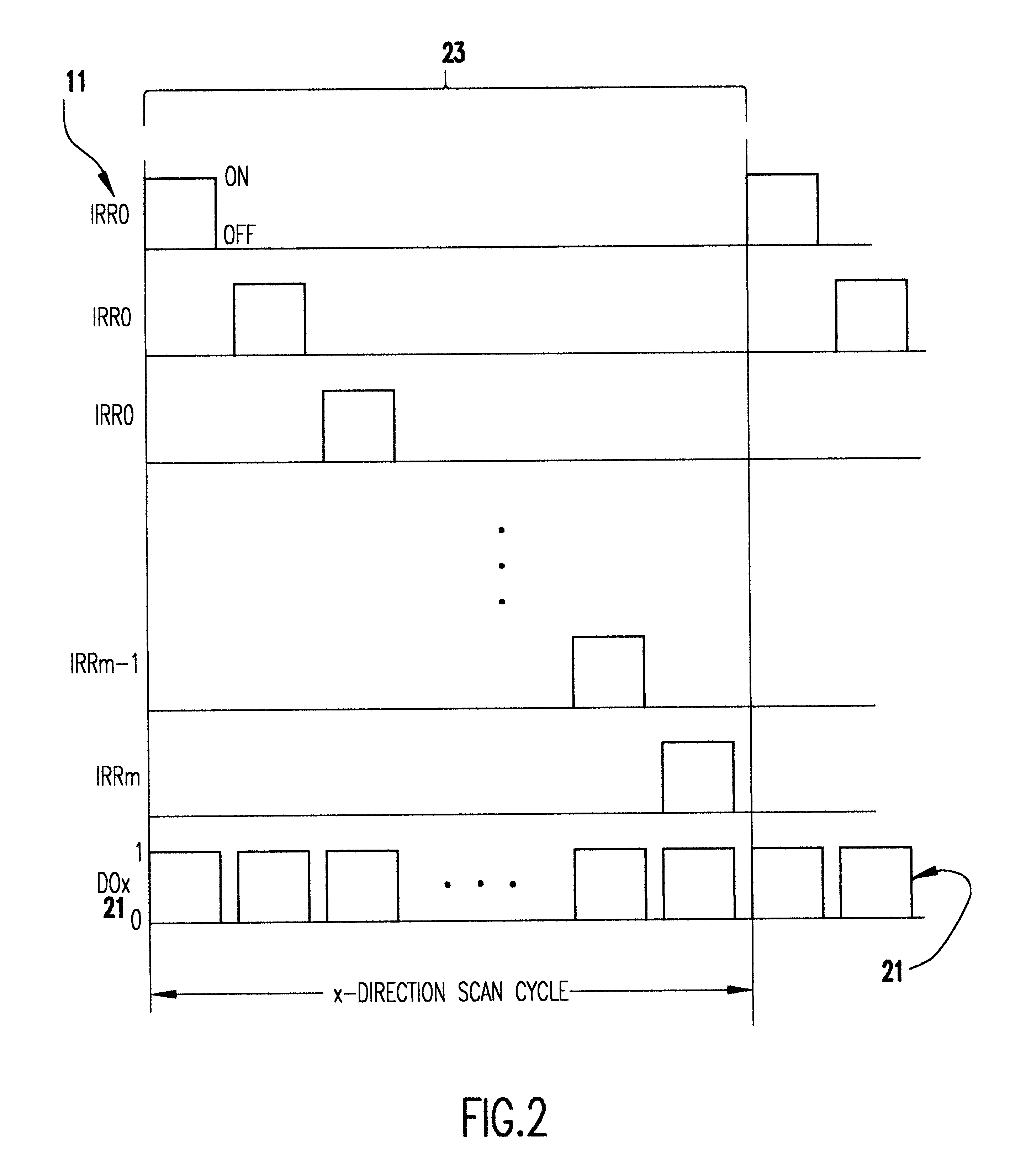
During operation, the FMA 15 is continuously scanned by IR light in both x and y directions from the IR lights sources 11 and 12. The x-direction IR source controller 16 sequentially activates the IR sources 11, while the y-direction IR source controller 17 sequentially activates IR sources 12. Although...


PUM


Abstract

Pointer positioning device based on infrared light sources and detectors that is compact, rugged and ergonomically easy to use such as can be used in laptop computers and similar devices. The pointer positioning device fits in the same area as a conventional touch-pad device in a portable computing device. It detects movement in a movement area by scanning for shadow information with infrared (IR) light sources. To increase the resolution of scanning and to avoid non-uniform beam widths, the scanning of the touchpad area may be carried out by using low power IR laser beams produced by a single IR laser source each for x and y directions and a plurality of optical fibers to transmit the laser beams in the x and y directions. Optionally, this divergency is minimized by positioning IR light sources and light detectors in an alternating pattern around the periphery of a movement area. A mouse device with an opaque plunger depressed with a finger is used as an object to create a well defined shadow in the x and y directions of a movement area.

Description

DESCRIPTION1. Field of the InventionThe present invention generally relates to pointer positioning devices and, more particularly, to an improved pointing device based on infrared light sources and detectors that is compact, rugged and ergonomically easy to use such as can be used in laptop computers and similar devices.2. Background DescriptionThe conventional mouse is a very useful device for moving the pointer on the computer displays and also for user input. However, for portable computers, it is desirable to provide a small compact input device which can provide the full functionality of the conventional mouse. Ergonomic convenience to the user is a paramount concern. Several types of pointer devices are currently available on different laptops and other portable computers. See S. Zhai, B. A. Smith, and T. Selker, "Improving Browsing Performance: A Study of Four Input Devices for Scrolling and Pointing Tasks," in Proceedings of INTERACT'97: The 6th IFIP Conference on Human-Comp...

Claims


Application Information

Patent Timeline
Patent Type & Authority Patents(United States)
IPC IPC(8): G06F3/033G06F3/042
CPCG06F3/03547G06F3/0421
Inventor ANVEKAR, DINESH KASHINATH
Owner LENOVO (SINGAPORE) PTE LTD
Learn More