System to pump fluid and control thereof

a technology of pumping system and fluid, applied in the field of pumping system, can solve the problems of increasing machine downtime, complicated use of hoses, pipes, fittings,

Active Publication Date: 2017-04-06
PROJECT PHOENIX
View PDF9 Cites 18 Cited by
  • Summary
  • Abstract
  • Description
  • Claims
  • Application Information

AI Technical Summary

Benefits of technology

[0006]Exemplary embodiments of the invention are directed to a pump having a fluid driver and to a method of delivering fluid from an inlet of the pump to an outlet of the pump using the fluid driver. The pump includes a casing defining an interior volume. The casing includes a first port in fluid communication with the interior volume and a second port in fluid communication with the interior volume. The fluid driver is disposed in the interior volume and includes a prime mover and a fluid displacement assembly. That is, unlike conventional pumps, both the prime mover and the fluid displacement assembly are disposed in the interior volume of the pump. Accordingly, pumps consistent with the present invention are less susceptible to contamination because components such as the prime mover and the fluid displacement assembly need not extend outside the pump casing. The prime mover drives the fluid displacement assembly and the prime mover can be, e.g., an electric motor, a hydraulic motor or other fluid-driven motor, an internal-combustion, gas or other type of engine, or other similar device that can drive a fluid displacement member. The prime mover can be variable-speed and / or a variable-torque device. By using a variable-speed and / or a variable-torque device for the prime mover, the flow control valve, variable piston pump, or some other flow control device can be eliminated because the prime mover can control the flow and / or pressure to the desired set point.
[0010]In another exemplary embodiment, a pump includes a casing defining an interior volume. The casing includes a first port in fluid communication with the interior volume and a second port in fluid communication with the interior volume. A first gear is disposed within the interior volume with the first gear having a plurality of first gear teeth. A second gear is also disposed within the interior volume with the second gear having a plurality of second gear teeth. The second gear is disposed such that a surface of at least one tooth of the plurality of second gear teeth meshes with a surface of at least one tooth of the plurality of first gear teeth. An electric motor, which is disposed in the interior volume, rotates the first gear about a first axial centerline of the first gear. The first gear is rotated in a first direction to transfer the fluid from the first port to the second port along a first flow path. The first gear rotates the second gear about a second axial centerline of the second gear in a second direction to transfer the fluid from the first port to the second port along a second flow path. In some embodiments, the second direction is opposite the first direction and the meshing seals a reverse flow path between the inlet and outlet of the pump. In some embodiments, the second direction is the same as the first direction and the meshing at least one of seals a reverse flow path between the inlet and outlet of the pump and aids in pumping the fluid.

Problems solved by technology

However, these hydraulic systems can be relatively large and complex.
To interconnect these parts, various additional components like connecting shafts, hoses, pipes, and / or fittings are used in a complicated manner.
Moreover, these components are susceptible to damage or degradation in harsh working environments, thereby causing increased machine downtime and reduced reliability of the machine.
However, these extended shaft and separate housing take up a significant amount of space and increase the weight of the pump.
In addition, the pumps may be susceptible to contamination due to components that extend outside the pump casing and / or fluid system.
Further, the extended shaft may require extra bearing(s) that need proper lubrication, which could increase structural complexity in the gear pump design.
Thus, known pumps and systems have undesirable drawbacks with respect to compactness, complexity and reliability of the systems.

Method used


Image

  • System to pump fluid and control thereof
  • System to pump fluid and control thereof
  • System to pump fluid and control thereof

Examples


Embodiment Construction

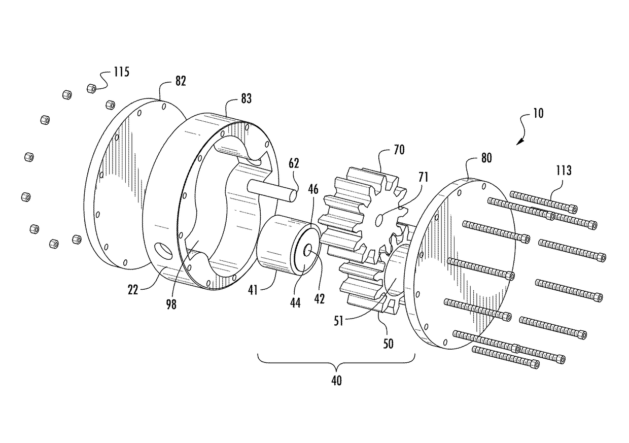
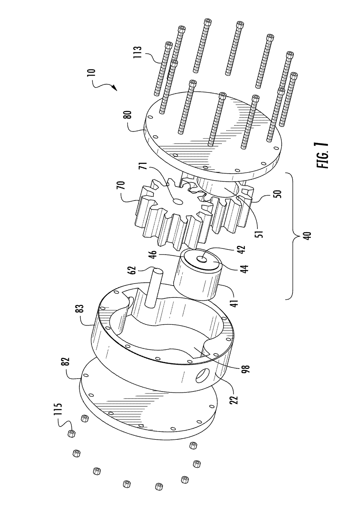
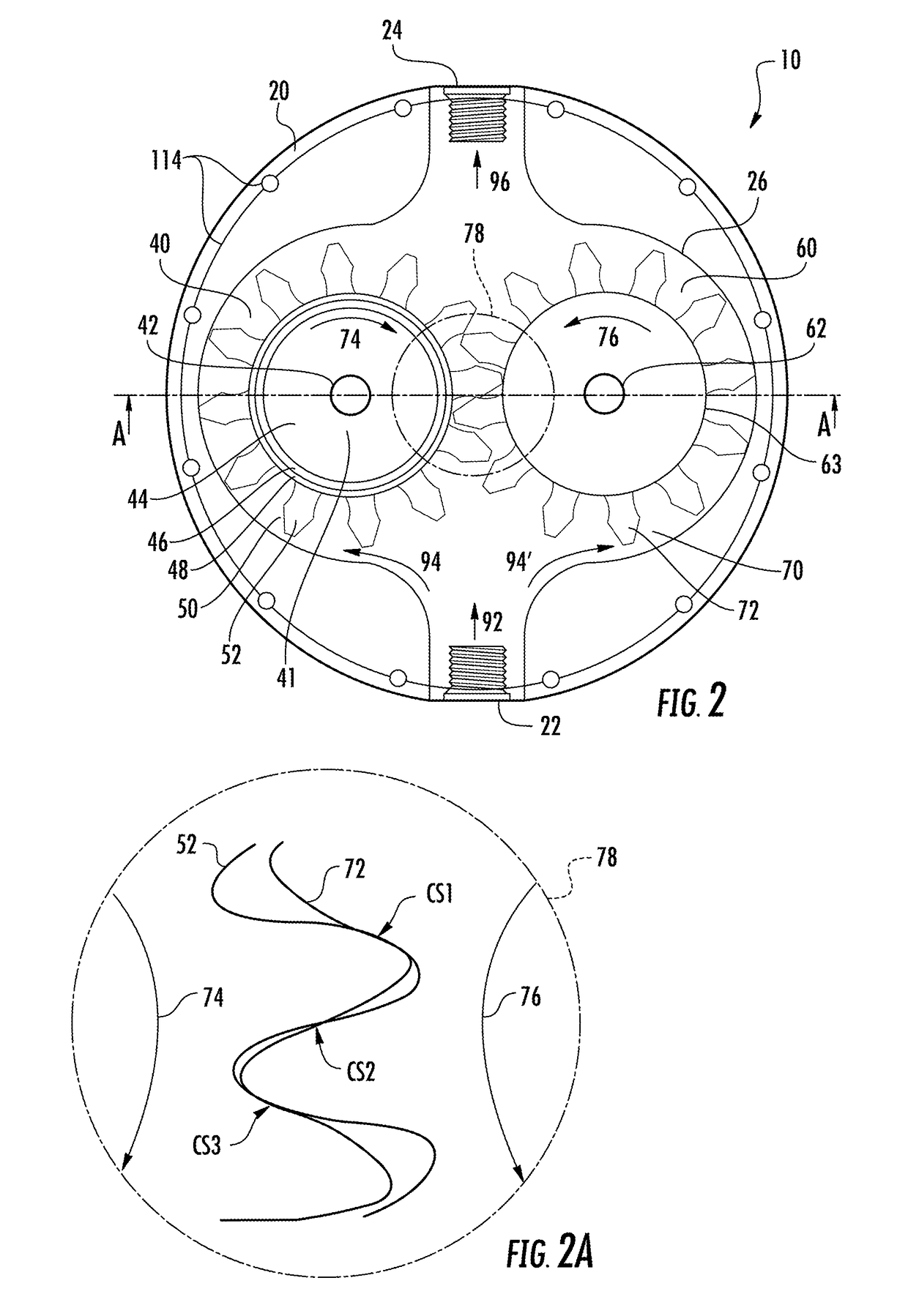
[0023]Exemplary embodiments of the present invention are directed to a pump where the fluid driver, which includes a prime mover and a fluid displacement assembly, is located entirely within the pump casing. In some embodiments, the prime mover is integrated with the fluid displacement assembly, e.g., the prime mover can be disposed internal to or within a component of the fluid displacement assembly. In other embodiments, the prime mover is located adjacent to the fluid displacement assembly but still within the pump casing. In some embodiments, the prime mover can be a variable-speed and / or a variable torque prime mover. Exemplary embodiments of the present invention are also directed to a system and method that provides for a more efficient and more precise control of the fluid flow and / or pressure in the system by using the variable-speed and / or variable-torque inventive pump. In some embodiments, the inventive pump is used to exclusively adjust the flow and / or pressure in the s...


PUM


Abstract

A pump having a fluid driver disposed within the interior volume of the pump and to a method of delivering fluid from an inlet of the pump to an outlet of the pump using the fluid driver. The fluid driver includes a variable-speed and / or a variable torque prime mover and a fluid displacement assembly. The pump can be used in a fluid pumping system to provide fluid to an actuator that is operated by the fluid. At least one of a speed and a torque of the pump is controlled so as to adjust at least one of a flow and a pressure in the fluid pumping system to a desired set point, without the aid of another flow control device.

Description

PRIORITY[0001]The present application claims priority to U.S. Provisional Patent Application Nos. 61 / 970,266 and 61 / 970,269 filed on Mar. 25, 2014; 62 / 006,750 and 62 / 006,760 filed on Jun. 2, 2014; 62 / 017,362 and 62 / 017,382 filed on Jun. 26, 2014; and 62 / 066,247 and 62 / 066,255 filed on Oct. 20, 2014, all of which are incorporated herein by reference in their entirety.TECHNICAL FIELD[0002]The present invention relates generally to various pumps, systems that pump fluid and to control methodologies thereof. More particularly, the present invention relates to a variable-speed, variable-torque pump with a fluid driver that is internal to the pump and control methodologies thereof in a fluid pumping system, including adjusting at least one of a flow and a pressure in the system using the pump and without the aid of another flow control device.BACKGROUND OF THE INVENTION[0003]Systems in which a fluid is pumped can be found in a variety of applications such as heavy and industrial machines,...

Claims


Application Information

Patent Timeline
Patent Type & Authority Applications(United States)
IPC IPC(8): F15B13/044F04C15/00F15B5/00F04C15/06F15B15/08F04C2/18F04C14/08
CPCF15B13/044F04C2/18F04C15/008F04C14/08F04C15/06F15B2211/763F15B5/006F04C2240/30F04C2240/40F04C2270/035F04C2270/051F15B15/08F04C11/008
Inventor AFSHARI, THOMAS
Owner PROJECT PHOENIX
Why Eureka
Try Eureka