
Fluidproof connector

a technology of connectors and connectors, applied in the direction of couplings/cases, coupling device connections, electrical appliances, etc., can solve the problems of dummy plugs moving back and adversely affecting sealing

Active Publication Date: 2017-04-06
SUMITOMO WIRING SYST LTD
View PDF4 Cites 3 Cited by
  • Summary
  • Abstract
  • Description
  • Claims
  • Application Information

AI Technical Summary

Benefits of technology

The invention provides a connector with a housing having a cavity for accommodating terminal fittings. The housing has a tapered surface around the cavity opening, and a pressing portion on a dummy plug which can be pressed against the tapered surface to prevent the dummy plug from moving forward. This prevents fluid or water from entering the housing. The pressing portion also has a larger surface in contact with the tapered surface to better seal the housing. The dummy plug can easily be pulled out to perform wiring harness assembly operations.

Problems solved by technology

However, the dummy plug may move back due to a high water pressure if the connector is exposed, for example, to washing water or the like injected at a high pressure.
Movement of the dummy plug toward the back of the cavity can adversely affect sealing.

Method used


Image

  • Fluidproof connector
  • Fluidproof connector
  • Fluidproof connector

Examples


first embodiment

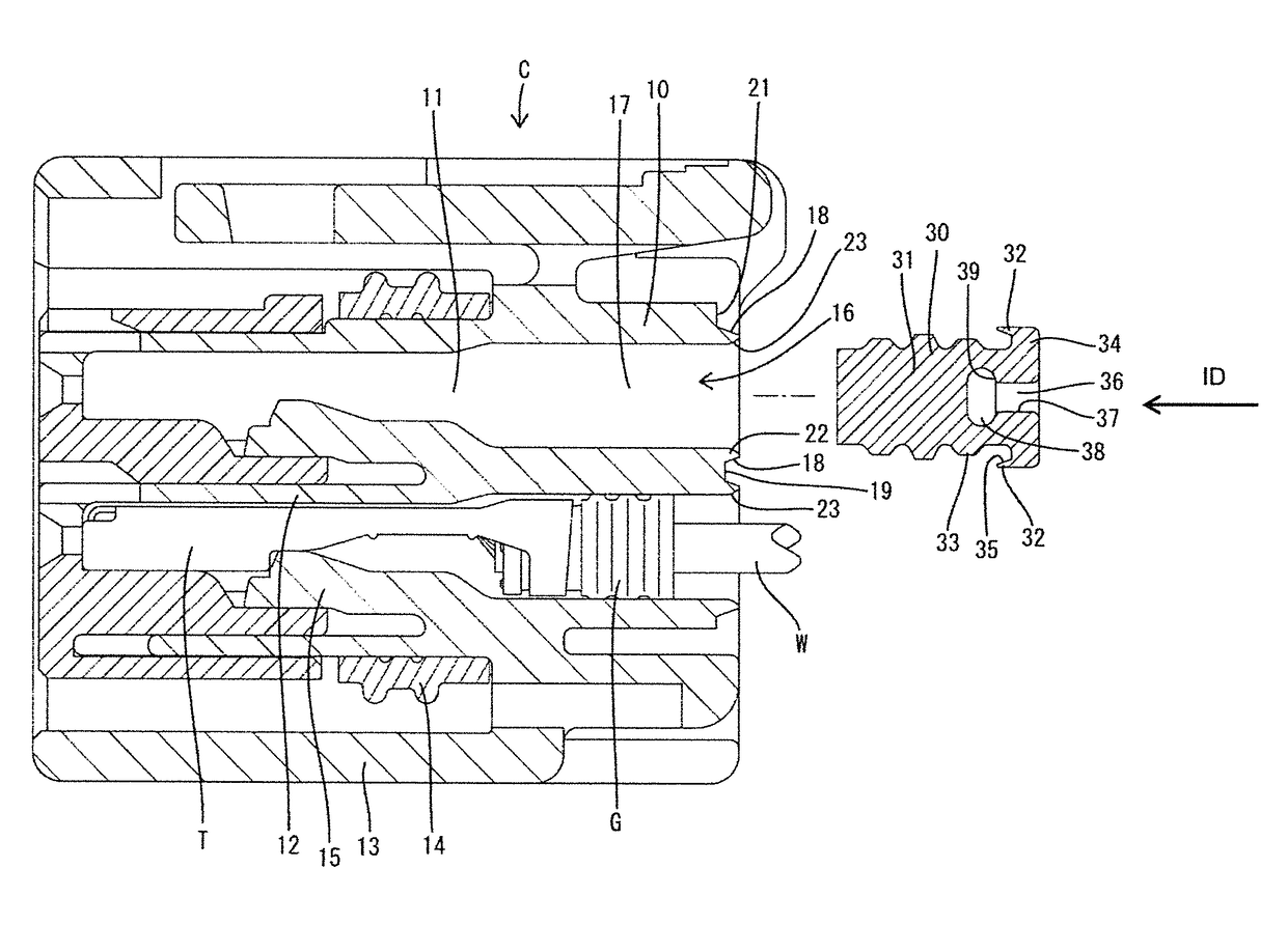
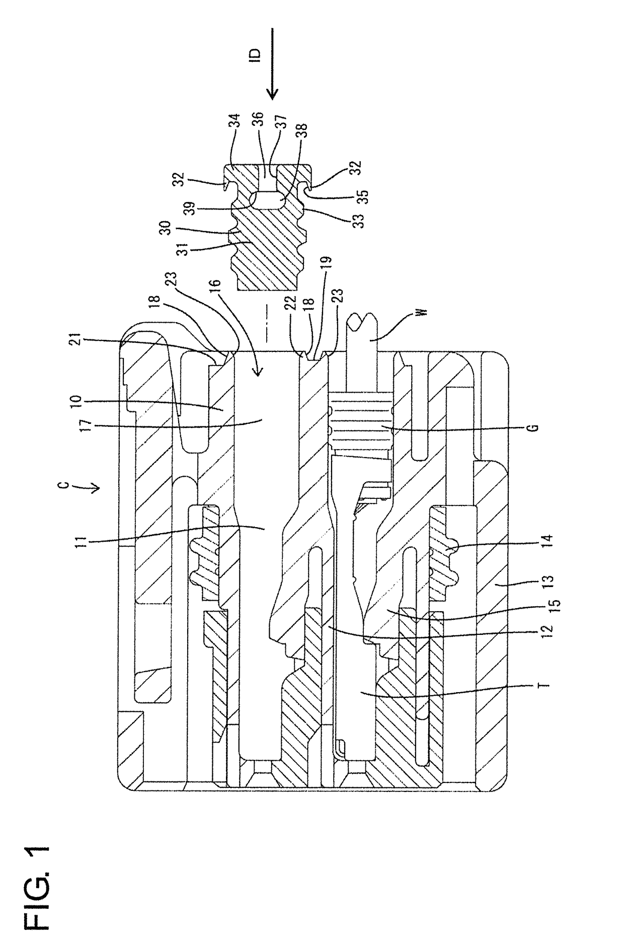
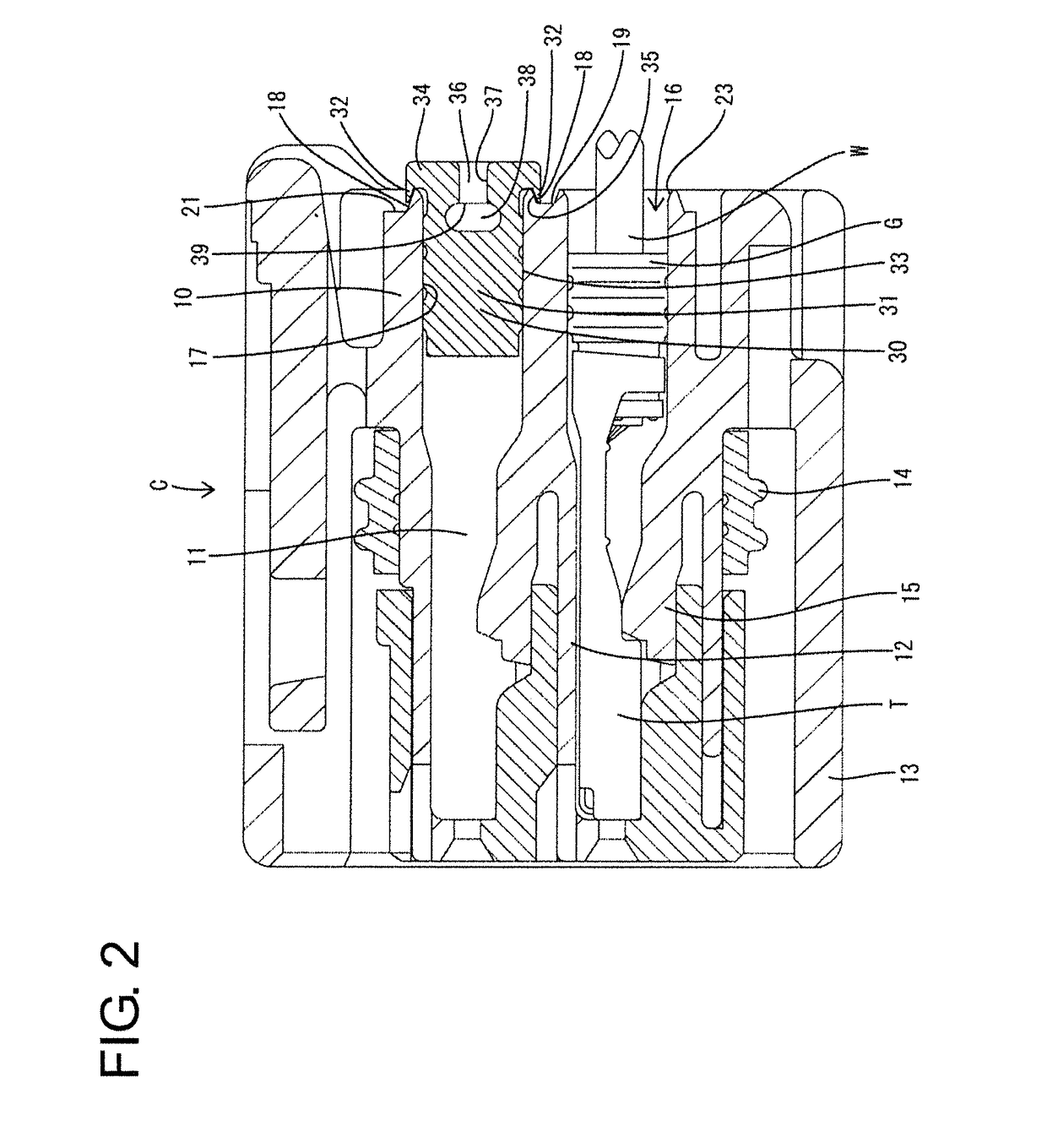
[0020]A fluid- or waterproof connector according to the invention is identified by the letter C in FIGS. 1 to 3. The connector C includes a housing 10 with cavities 11 capable of accommodating terminal fittings T and a dummy plug 30 to be inserted into at least one of the cavities 11 that has no terminal fitting T accommodated therein. In the following description, an inserting direction ID of the dummy plug 30 into the housing 10 is referred to as a forward direction, an opposite direction is referred to as a backward direction and upper and lower sides of FIG. 1 are referred to as upper and lower sides.

[0021]The housing 10 is made e.g. of synthetic resin and includes a terminal accommodating portion 12 provided with cavities 11 and an outer tube 13 at least partly surrounding the outer periphery of the terminal accommodating portion 12. An annular fluid- or waterproof seal 14 is to be provided between the terminal accommodating portion 12 and the outer tube portion 13 for sealing ...

second embodiment

[0051]When the dummy plug 30 of this second embodiment is pushed forward into the cavity 11 through the opening 16, the pressing projection 42 of the pressing portion 41 is held proximate to the tapered surface 18. If the fluid- or waterproof connector 40 is placed in an environment to be subjected to a high fluid or water pressure (such as during high-pressure washing) and the high water pressure acts on the rear surface of the dummy plug 30, the pressing projection 42 is pressed against the tapered surface 18 to be resiliently squeezed and held in close contact with the tapered surface 18, thereby preventing water intrusion through between the pressing portion 41 and the tapered surface 18.

[0052]As described above, in this second embodiment, the tapered surface 18 is formed on the rear surface of the housing 10 to substantially surround the opening 16 of the cavity 11 and the dummy plug 30 is provided with the pressing portion 41 to be pressed against the tapered surface 18. Thus,...


PUM


Abstract

A waterproof connector includes a housing (10) provided with cavities (11) capable of accommodating terminal fittings (T) and open backward, a dummy plug (30) configured to be held in close contact with an inner surface of the cavity (11) by being inserted into the cavity (11) from behind, tapered surfaces (18) formed on a rear surface of the housing (10) to surround openings (16) of the cavities (11) and inclined to come closer to the inner surfaces (17) of the cavities (11) toward the back, and a pressing portion (32) provided on the dummy plug (30) and configured to be pressed against the tapered surface (18) by a forward force acting on the dummy plug (30).

Description

BACKGROUND[0001]1. Field of the Invention[0002]The invention relates to a fluidproof connector.[0003]2. Related Art[0004]A conventional waterproof connector has a housing with cavities to accommodate terminal fittings that are connected to ends of wires. Openings of the cavities are closed by waterproof rubber plugs fit on end parts of wires. A dummy plug may be used instead of the waterproof rubber plug to close a cavity left empty without having a terminal fitting inserted therein.[0005]Japanese Unexamined Patent Publication No. 2009-170233 discloses a waterproof connector with a dummy plug that is fit into an empty cavity. The dummy plug has a cylindrical main body and lips on the outer peripheral surface of the main body. The dummy plug is deformed entirely in a diameter reducing direction when being pushed into the cavity, thereby being held in close contact with the inner surface of the cavity over the entire circumference. However, the dummy plug may move back due to a high w...

Claims


Application Information

Patent Timeline
Patent Type & Authority Applications(United States)
IPC IPC(8): H01R13/52
CPCH01R13/52H01R13/5202H01R13/5213
Inventor SUZUKI
Owner SUMITOMO WIRING SYST LTD
Learn More