
Hydraulically Propelled Drone for Delivering Firefighting fluid

a hydraulically propelled drone and firefighting technology, applied in the direction of tethered aircraft, aircraft navigation control, transportation and packaging, etc., can solve the problems of firefighters being routinely at risk of injuries, limited vehicle value for fires located in high-rise buildings or other locations, and extraordinary danger in firefighting

Inactive Publication Date: 2017-04-27
HEIN KIM F
View PDF1 Cites 33 Cited by
  • Summary
  • Abstract
  • Description
  • Claims
  • Application Information

AI Technical Summary

Benefits of technology

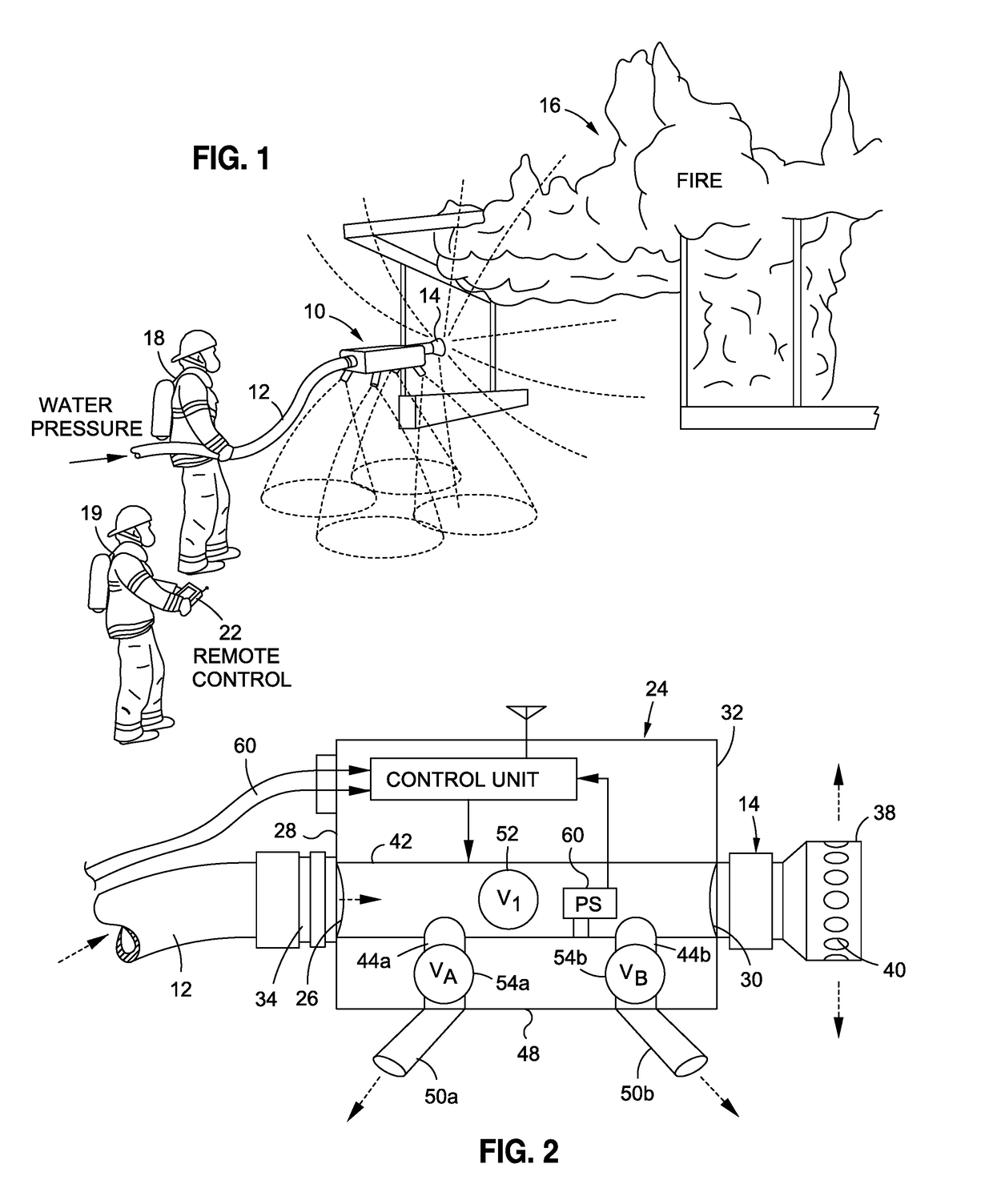
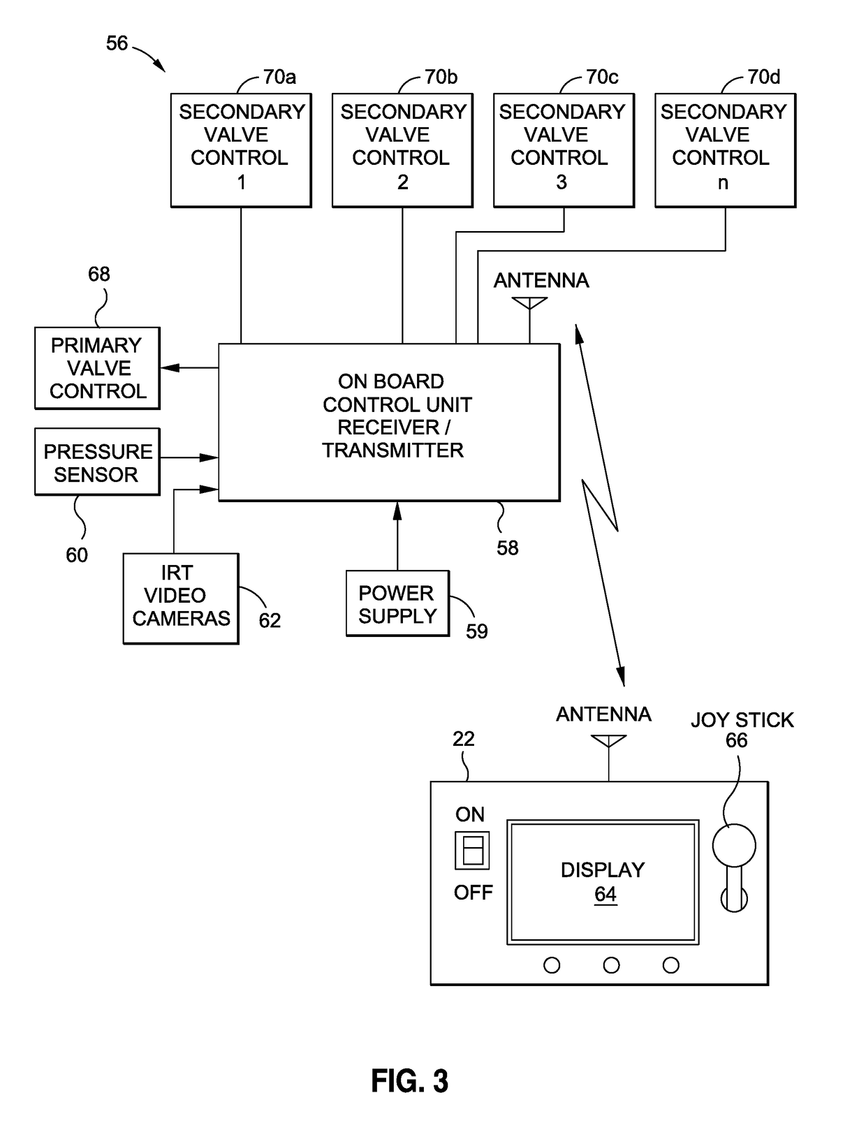
The present invention relates to a hydraulic drone for delivering firefighting fluid to elevated locations. The drone has a housing with a primary inlet for receiving the end of a fire hose, a primary outlet for receiving the end of a primary nozzle, a central passageway for conducting fluid from the primary inlet to the primary outlet, and at least one secondary outlet communicating with the central passageway. The drone has at least one lift nozzle that directs fluid in a generally downward direction to produce an upward thrust on the drone housing. The drone has a control system to open and close the valves to control the flow of fluid through the nozzles. The lift nozzle may be angled to produce a forward or rearward thrust. The drone may also have a rotatable steering nozzle on top of the housing for controlling horizontal movement. The technical effect of the invention is to provide a firefighting drone that can deliver firefighting fluid to elevated locations with increased efficiency and safety.

Problems solved by technology

Firefighting is an extraordinarily dangerous activity.
Firefighters are routinely at risk of injuries due to high heat, smoke inhalation, exposure to hazardous materials, structural collapse, and falling debris.
However, such vehicles have limited value for fires located in high-rise buildings or other locations above ground level.
Aerial firefighting vehicles such as helicopters and airtankers, or water bombers, have been used to drop water or fire retardant on wildfires, but such vehicles are very expensive and require skilled pilots.

Method used


Image

  • Hydraulically Propelled Drone for Delivering Firefighting fluid
  • Hydraulically Propelled Drone for Delivering Firefighting fluid
  • Hydraulically Propelled Drone for Delivering Firefighting fluid

Examples


Embodiment Construction

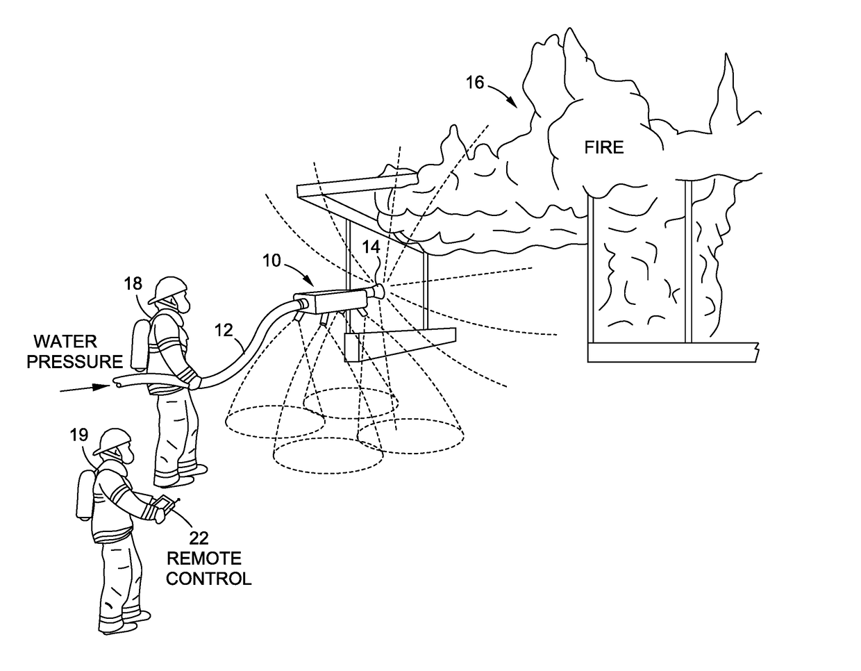
[0025]Turning now to the drawings, in which like numerals indicate corresponding elements throughout the several views, attention is first directed to FIG. 1, showing the nozzle drone of the present invention, indicated in its entirety by the numeral 10, being used to transport a fire hose 12 and primary nozzle 14 to the scene of a structure fire 16. The nozzle drone 10 allows firefighting fluid such as water, fire retardant foam, or a combination of fire retardant foam and water, to be delivered to the hottest and most hazardous area of the fire 16, while allowing firefighting personnel 18, 19 to remain a safe distance away from the collapse zone of the burning structure 20. Movement of the nozzle drone 10 and flow through the primary nozzle 14 is controlled by an operator 19 using a remote control handset 22.

[0026]The hose 14 may be any type of non-collapsible fire hose, such as a supply hose, relay hose, attack hose, booster hose, or forestry hose, and may be connected to a remot...


PUM


Abstract

A hydraulically propelled drone is provided for delivering firefighting fluid to an elevated location. The drone comprises a housing having a primary inlet configured to receive the distal end of a fire hose, a primary outlet configured to receive the inlet end of a primary nozzle, a central passageway configured to conduct fluid from the primary inlet to the primary outlet, and at least one secondary outlet communicating with the central passageway. At least one lift nozzle communicates with the secondary outlet and is configured to direct fluid in a generally downward direction so as to produce an upward thrust on the drone housing, and at least one valve is contained within the housing and configured to control the flow of said fluid through the primary nozzle and the at least one lift nozzle nozzle.

Description

CROSS REFERENCE TO RELATED APPLICATIONS[0001]This is a continuation-in-part of U.S. patent application Ser. No. 14 / 923,928, filed Oct. 27, 2015.FIELD OF THE INVENTION[0002]This invention relates to the field of firefighting equipment.[0003]More specifically, the invention relates to an apparatus for delivering firefighting fluid to an elevated location.[0004]In a further and more specific aspect, the invention concerns a hydraulically propelled drone for delivering firefighting fluid to an elevated location.BACKGROUND OF THE INVENTION[0005]Firefighting is an extraordinarily dangerous activity. Firefighters are routinely at risk of injuries due to high heat, smoke inhalation, exposure to hazardous materials, structural collapse, and falling debris. As result, various attempts have been to design firefighting equipment that can be controlled remotely, allowing firefighters to keep a reasonable distance from the hottest, most dangerous regions of a fire zone. For instance, US patent ap...

Claims


Application Information

Patent Timeline
IPC IPC(8): B64C15/02B64C39/02
CPCB64C15/02B64C39/024B64C2201/12B64C2201/10B64C39/022A62C31/03A62C31/05B64U30/30B64U2101/47B64U50/16B64U10/13B64U30/00B64U2101/00
Inventor HEIN, KIM F.
Owner HEIN KIM F
Learn More