Eureka AIR delivers breakthrough ideas for toughest innovation challenges, trusted by R&D personnel around the world.

Total control perforator and system

a perforator and total control technology, applied in the field of industrial art, can solve the problems of no economically viable production, all wells exhausting their purpose and being abandoned, and depleting the production strata,

Active Publication Date: 2017-04-27
YELLOWJACKET OILFIELD SERVICES LLC
View PDF3 Cites 4 Cited by
  • Summary
  • Abstract
  • Description
  • Claims
  • Application Information

AI Technical Summary

Benefits of technology

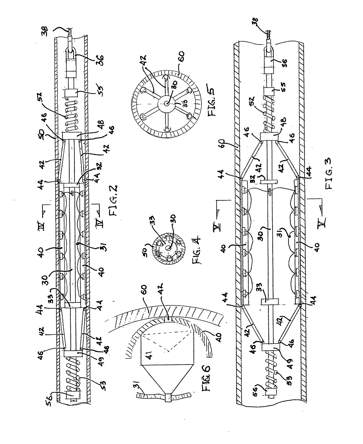
The present perforating tool is designed to carry multiple perforation charges and can fit inside a smaller riser pipe and expand into a larger casing. It uses a central tube and framing discs to support the charges, with hinge carriers and radius rods to provide radial bias on the charges. The charges are secured along the inside length of the tool and are compressed against the bias of coil springs for transit through the riser bore. Once in the larger casing, the coil springs expand the charges to make contact with the casing surface for final placement and discharge of the charges. The technical effect of this design is a more efficient and effective tool for perforating oil and gas wells.

Problems solved by technology

Eventually, all wells exhaust their purpose and are abandoned.
Either the well is a “dry hole”, having no economically viable production, or has depleted the production strata.
Inadequate cement jobs and deterioration of cement over time can lead to flow paths being opened through an otherwise solid cement barrier.
However, deep water offshore wells present unique difficulties for this alternative procedure.
By the time of well abandonment, platforms such as was used for the original drilling, are not economically available.
In many deep water wells, however, even the smallest or innermost casing is larger than the riser capacity of most maintenance ships.
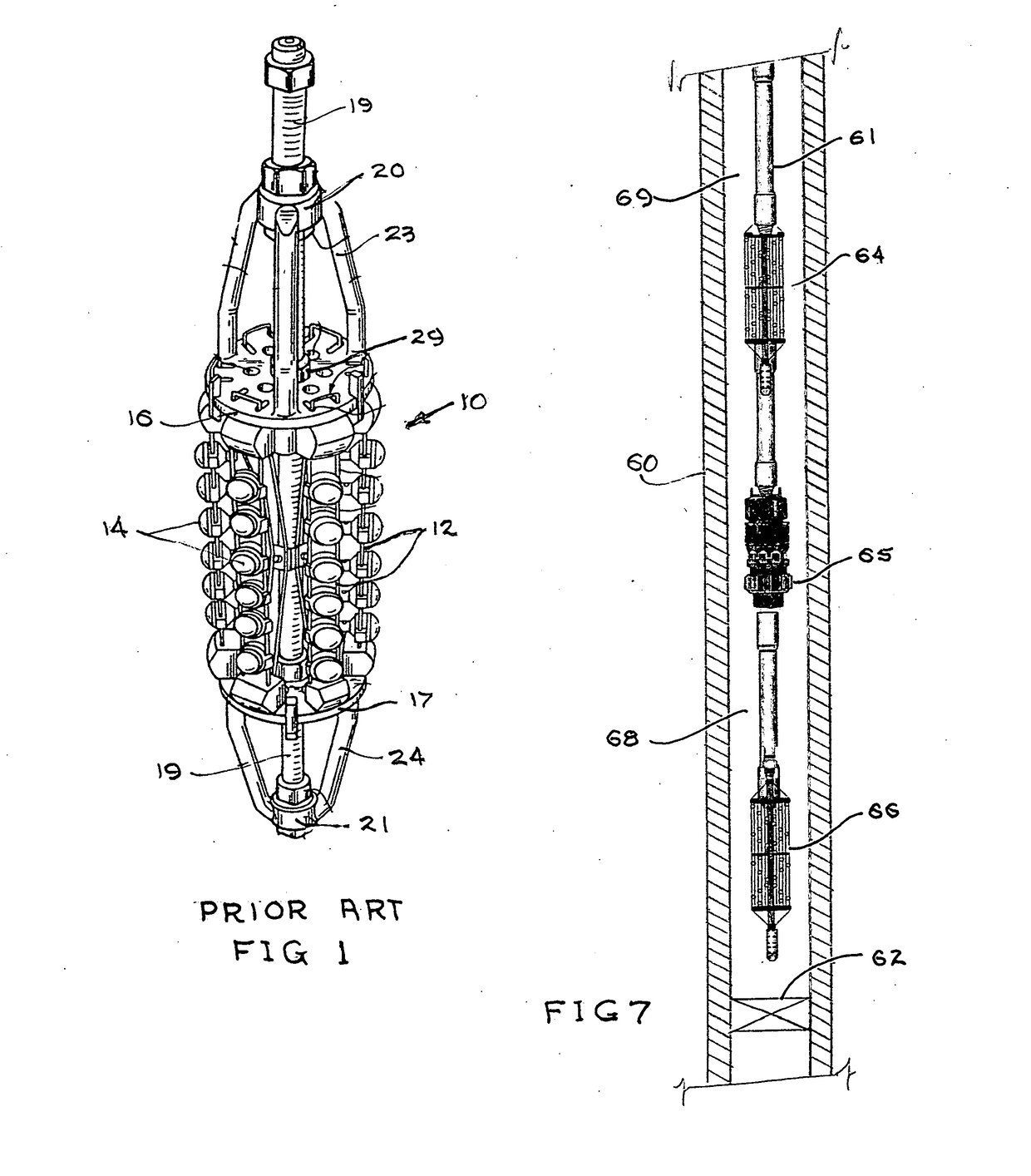
An example of such a resiliently biased perforating gun is disclosed in U.S. Pat. No. 5,295,544 to D. V. Umphries. However, the radial expansion distance of a prior art resilient bar is insufficient to accommodate the radial difference between a 6⅝″ maintenance ship riser and a 24″ casing.

Method used


Image

  • Total control perforator and system
  • Total control perforator and system
  • Total control perforator and system

Examples


Embodiment Construction

[0027]As used herein, the terms “up” and “down”, “upper” and “lower”, “upwardly” and downwardly”, “upstream” and “downstream”; “above” and “below”; and other like terms indicating relative positions above or below a given point or element are used in this description to more clearly describe some embodiments of the invention. However, when applied to equipment and methods for use in wells that are deviated or horizontal, such terms may refer to a left to right, right to left, or other relationship as appropriate. Moreover, in the specification and appended claims, the terms “pipe”, “tube”, “tubular”, “rod”, “casing”, “liner” and / or “other tubular goods” are to be interpreted and defined generically to mean any and all of such elements without limitation of industry usage.

[0028]In describing a preferred embodiment of the invention illustrated in the drawings, specific terminology will be resorted to for the sake of clarity. However, the invention is not intended to be limited to the ...


PUM


Abstract

A shaped charge carrier tool is provided that has particular utility for perforating well casing as a preparation for cement placement. A plurality, four or more elongated shaped charge carrier ribs having a high bending modulus are secured for radially expanded displacement around a central framing tube or rod. Radius rods link the ends of the carrier ribs to top and bottom hinge carriers. The hinge carriers encircle the framing tube and are free for axial translation along the framing tube. Articulating hinges connect the radius rods to the carrier ribs and to the hinge carriers. Opposed compressed coil springs provide a resilient bias on the hinge carriers to translate the carrier ribs radially outward against the interior surface of a well casing as the tool passes from a riser tube into a larger inside diameter well casing.

Description

CROSS-REFERENCE TO RELATED APPLICATION[0001]Not applicableBACKGROUND OF THE INVENTION[0002]Field of the Invention[0003]The present invention relates to the industrial art of earth-boring and well drilling for the recovery of fluid minerals. More particularly, the invention relates to a carrier for a multiplicity of shaped explosive charges to penetrate well casing with multiple apertures.[0004]Description of Related Art[0005]In the oil and gas industry, well plugging operations are often performed to seal wellbores in order to abandon the wells. Eventually, all wells exhaust their purpose and are abandoned. Either the well is a “dry hole”, having no economically viable production, or has depleted the production strata. In either case, a non-productive well is or should be permanently “plugged”. “Plug and abandonment” procedures are required under various state and federal laws and regulations. Plug and abandonment operations performed upon a cased wellbore require that at least a se...

Claims


Application Information

Patent Timeline
IPC IPC(8): E21B43/117E21B47/06E21B23/06E21B33/12
CPCE21B43/117E21B33/12E21B33/13E21B23/06E21B33/134E21B47/06E21B43/119E21B47/005
Inventor UMPHRIES, DONWILLIGER, GABE
Owner YELLOWJACKET OILFIELD SERVICES LLC
Why Eureka
Eureka Blog
Learn More